
How to Plan a Pergola on a Sloping Terrace
Pergola planning
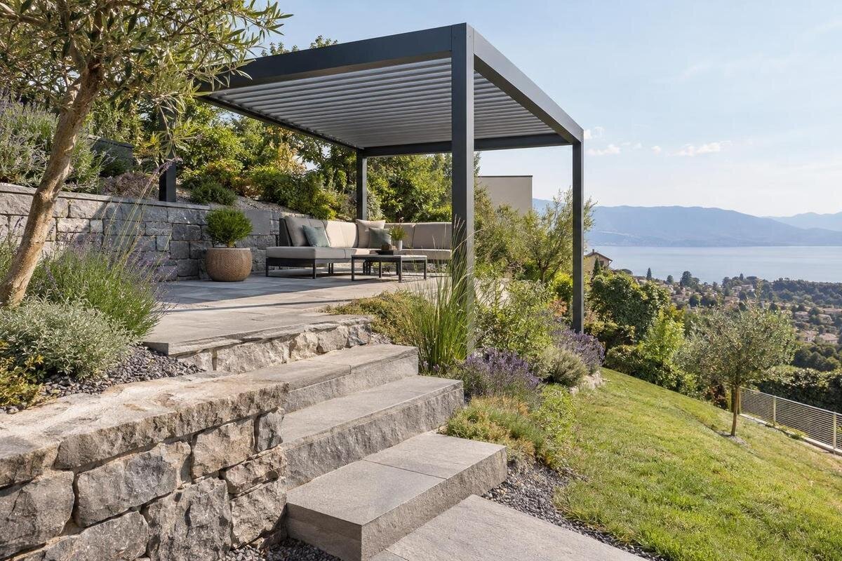
A sloping terrace does not automatically rule out a pergola, but it changes more than the height of one post. The key distinction is between the fall built into the terrace to manage surface water and the roof line specified for the pergola model. Survey the finished surface, set out the approved post positions and check the roof clearances as one plan. A footprint that looks straightforward on a flat sketch may need a different assessment on site.
01
Terrace fall and pergola roof level are separate
A terrace fall and a pergola roof level solve different problems. The fall across paving is generally part of surface-water management; the roof line belongs to the selected model’s design. They meet at the posts, but they are not the same plane. A frame should not automatically be tilted to match the paving, and a level roof should not be assumed possible with every model. First establish what roof orientation the model’s approved drawing allows, then compare that geometry with the actual surface levels. This keeps a useful drainage fall from being mistaken for an instruction about the roof.
Think of three separate things: the finished terrace surface, the support connection heights and the roof perimeter. The surface rises or falls underfoot; the roof may stay level, follow a specified pitch or use another approved arrangement. Where the approved design calls for a level roof across sloping ground, the supports must accommodate the difference, but how that is done is model-specific. Consider the roof’s underside as well as its outside edge. That makes it easier to identify a clearance issue near a doorway, window or walking route before a model is ordered.
Survey the finished surface at every proposed post
Record the finished surface level at each intended post position, not just at the two ends of the terrace. Also note steps, ramps, thresholds and any change in paving level within the footprint. A single end-to-end estimate can miss cross-fall or a local hollow, so it may not show what the surface is like beneath every support. A site assessor can use a shared reference level to describe these points consistently. Label each proposed post on the sketch and use the same labels alongside the measurements, so there is no doubt about which level belongs to which position. Describe the direction of the fall as well as the difference in height: a terrace that falls away from the house needs to be represented differently from one that falls along it. If the paving is not down yet, include its planned finished height rather than relying only on the current base or soil level. Keep planned and existing levels clearly identified.
Set out the proposed footprint from the exact model plan, then relate each post position to the measured terrace levels. The Bloomcabin Bioclimatic Pergola listing is stated as ranging from 9 to 24 m². That area can help describe the listed model options, but it does not show post centres, permitted height changes or whether a particular slope can be accommodated. For those questions, use the drawing for the chosen configuration and the site measurements together.
02
Confirm the roof line and clearances for the model
Use the model’s approved drawing to establish whether its roof must be level, may be installed in a specified orientation or has another permitted arrangement. Do not infer the required angle from a product image or from the direction of the paving fall. Check which reference points define the roof height, and compare the underside and perimeter with the terrace at both the uphill and downhill sides. This matters near doors and windows, under eaves, and wherever people need to walk. Distinguish the overall roof height from the clearance beneath it; they describe different parts of the proposed installation. On the site sketch, identify the specific roof edge or underside point being compared with each nearby opening. This makes the comparison useful rather than leaving a single height figure that could refer to several places. A roof that looks clear from one viewpoint may still conflict with an opening or overhead feature elsewhere.
Include the surfaces and openings around the proposed roof, not just the four post positions. If a wall-side option is being considered, the Bloomcabin Wall-Mounted Pergola listing identifies the model to discuss, but its name alone does not establish a suitable roof height or fit beside a particular building. Ask for the drawing for the exact configuration and have its clearances checked against the site. Where the model has a defined operating envelope, include that space in the assessment too.
Keep the post layout within the approved drawing
Once you have a model in mind, compare its approved post positions with the measured terrace plan. A roof outline alone is not enough: the supports need to land where the design allows them to, and the fall does not give you permission to move one post sideways or stretch the frame. Mark the actual support positions, rather than estimating them from the outside edge of the roof. If the drawing gives a particular reference for post centres or bases, use that reference when checking the layout with an installer. Keep the roof perimeter and the support positions distinguishable on the sketch, particularly where either is close to a terrace edge. When comparing alternative locations, move the complete proposed layout on the plan rather than redrawing individual posts to avoid obstacles. This lets you compare possible positions without accidentally presenting a modified support arrangement as the original design.
Look for conflicts with drains, service covers, paving joints, steps, edges and paths before settling the footprint. A support landing over a drain or close to an edge is a reason to get the proposed arrangement assessed, not to shift it independently. If the Bloomcabin Pergola range is on your shortlist, ask for the approved post plan for the selected version and compare it with the measured terrace. If the layout does not fit, reconsider the model or its position before work begins.
03
Plan the post-to-surface connection for changing levels
If the approved roof line is level across a sloping terrace, the height between the finished surface and the roof will differ between support points. That is a consequence of the levels, not permission to cut, extend, tilt or pack posts. Do not assume that every post can be adjusted independently, or that an arrangement shown for one model applies to another. Separate the required height at each position from the method proposed to achieve it. The first describes the site geometry; the second must stay within the model’s permitted arrangement. An enquiry that simply asks whether the posts are adjustable leaves out the measured difference and where it occurs. Provide those details so the answer relates to the intended layout, not a general description of the product. Ask whether the exact model has an approved way to accommodate that difference and have the proposed solution confirmed before installation.
The contact between each support and the finished surface also needs checking. On a slope, the surface beneath a support may fall away across its footprint, so the paving alone does not confirm that the base and anchoring arrangement is suitable. Avoid relying on improvised packing or other unapproved changes to make the pieces appear level. For the Bioclimatic Pergola model, as for any shortlisted option, ask which support detail is approved for the exact model and site conditions.
Map terrace drainage separately from roof runoff
Mark the direction water travels across the terrace, along with channel drains, gullies, low points, downpipes and door thresholds. A post or its support may occupy space needed for a drainage route or access to a drain, so check the proposed positions against those features. Show where water is intended to leave the terrace, not just the direction it initially flows. This helps distinguish a clear route across the paving from a route that ends at an obstruction or an opening. Roof water is a separate consideration: depending on the chosen design, it may be collected or shed at particular edges. Put the terrace route and the proposed roof discharge points on the same sketch, while keeping them clearly labelled. That allows the assessor to consider how they meet without assuming the two systems share an outlet. Check the model information rather than assuming that a gutter, outlet or particular discharge direction is included.
When reviewing the Wall-Mounted Pergola model, ask which roof edges or outlets, if any, need to be considered for the selected configuration. Then assess where that water would go in relation to the terrace’s existing drainage and nearby openings. Keep drains accessible and consider the route water takes across the paving as well as from the roof. If the terrace already holds water, have the drainage issue assessed rather than treating a pergola support or roof as a fix for it.
04
Confirm the supporting structure beneath the surface
A finished paved surface does not show what lies beneath it or confirm that the underlying construction can support an anchored pergola. Beneath the finish there may be a slab, a compacted base, a structural deck or a different build-up, and conditions can vary across one terrace. A support near an edge or step may need particular attention. Gather any useful construction records and make clear which parts of the surface are known and which are not. Relate that information to the proposed support positions: knowing the construction in one part of the terrace does not describe every other part. If a record covers only an earlier terrace area, identify that limit rather than applying it to an extension as well. This keeps the enquiry focused on the ground or structure beneath each proposed connection. The appearance of the paving is not evidence of the material or structure below it.
Provide that information to the installer or a qualified structural professional so the proposed anchoring can be assessed against the exact model and site. The review should use substrate evidence and approved anchoring drawings, not a guessed footing size based on the pergola’s area or the amount of slope. When enquiring about Bloomcabin’s Bioclimatic Pergola, include the measured support positions and information about the surface build-up. The anchoring proposal needs to suit the model and the actual conditions at those points.
Check access and usable space on both sides
Walk the terrace from the uphill and downhill approaches and mark the routes people use. Include doors and their opening paths, stair landings, steps, furniture and any narrow points between the house and the terrace edge. The roof-to-surface clearance can vary across a slope, so check both ends of each route rather than judging from one standing position. Consider the approach to a seat as well as the space occupied by the furniture itself. A dining layout, for example, needs to be assessed with chairs in use, not only tucked beneath the table. Mark where those movements overlap a post position or a route to the steps. Keeping these everyday movements on the same plan helps you compare layouts without treating all space beneath the roof as equally usable. A post may also affect a doorway or make a previously clear path awkward, even when the roof outline appears to fit within the terrace.
Allow for the actual post positions when assessing the space available for seating and movement; the roof footprint is not the same as unobstructed floor area. If the Bloomcabin Wall-Mounted Pergola is under consideration, compare the approved layout for the selected configuration with the routes and usable space you have marked. Do not rely on the model name or an area figure to establish how much room remains between the supports, the building and the downhill edge.

05
Locate edges, boundaries and existing services
Add fixed features to the site plan: building eaves, windows, outside lights, downpipes, fences, service covers, terrace edges and retaining structures. A slope can change the relationship between the roof and those features at different heights, even when the footprint appears clear on a plan. Check the uphill and downhill edges as well as the post positions. Leave access to drains and services in the assessment, and do not treat an existing wall or retaining structure as a suitable support or fixing point without having it assessed.
Share relevant edge distances and obstructions with the person reviewing the installation, so the roof outline and support layout can be checked together. The Bloomcabin Pergola product page can identify the model you are asking about; its exact approved plan still needs to be compared with the measured site. A top-down plan shows where features sit beside the footprint, while a side view can clarify their relationship to the proposed roof height. Use both where a nearby feature is difficult to describe with a distance alone. If a boundary, nearby structure or service creates a concern, resolve that in the site review rather than assuming a clearance visible from the paving will remain adequate at roof height.
Bring the site levels and installation plan together
Prepare one coordinated set of information: a sketch of the finished terrace, the direction of its fall, measured levels at the proposed posts, and the locations of drains, steps and thresholds. Add the selected model and its exact approved post layout, plus what is known about the construction beneath the surface. If the terrace finish is not installed yet, identify its planned finished height. This gives the installer or assessor a shared view of the roof line, support points, clearance needs and surface-water routes rather than a collection of separate estimates.
Before committing to the layout, resolve a few specific questions: what roof orientation is approved for this model; what clearances will remain at the uphill and downhill sides; can its post arrangement accommodate the measured levels; and what anchoring proposal suits the substrate? Also confirm how terrace drainage and any roof runoff will be managed. Keep the answers with the relevant drawing so the intended layout is clear to everyone involved. If no approved arrangement fits the site, revisit the model or position instead of leaving the adjustment to installation day.
Frequently asked questions
Can a pergola be installed on any sloping terrace?
There is no universal answer. It depends on the exact model, the measured levels, the approved post arrangement and what lies beneath the terrace surface. Have the proposed layout assessed for that site before assuming the slope can be accommodated.
Should the pergola roof follow the terrace fall?
Not automatically. The terrace fall is part of the surface-water plan, while the roof orientation is determined by the selected model’s design. Check the approved drawing; do not tilt the frame to match the paving unless that arrangement is expressly allowed.
Can posts be cut or adjusted to compensate for the slope?
Only if the exact model’s approved instructions allow the proposed adjustment. Different surface levels may create different distances between the terrace and roof, but that is not permission to cut, extend, tilt or pack posts. Ask for the permitted arrangement before installation.
Will a pergola change terrace drainage?
It can affect where water can flow, because posts or supports may meet existing drainage routes. The roof may also collect or shed water in a way that differs from the open terrace. Check both water paths and keep drains accessible.
What should I provide when asking for a site assessment?
Share the finished terrace levels at the proposed post positions, the selected model and its approved layout, information about the construction beneath the surface, and the locations of drains, steps and thresholds. This gives the assessor a basis for reviewing the clearances and anchoring.
A sound plan keeps the terrace fall, pergola roof line and post arrangement distinct until they have been checked together. Let the terrace continue to manage surface water, use the chosen model’s approved drawing to establish the roof and support layout, and assess that layout against the measured surface and underlying structure. The result should be a design that fits the site as it is, rather than a frame altered by guesswork to suit the slope.
