
Planning Pergola Fixings for an Insulated Wall
Pergola installation planning
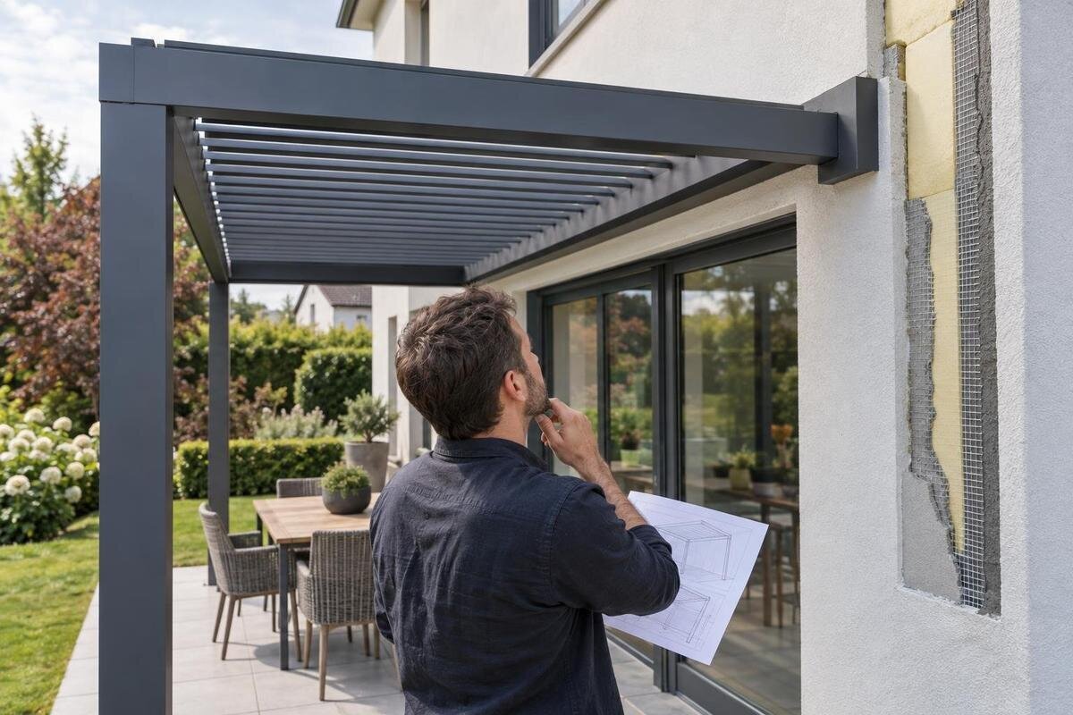
Fixing a pergola to a wall finished with external insulation is not a matter of choosing a longer screw. The visible render and insulation are part of a façade build-up, while the support must ultimately transfer the pergola’s forces into a suitable structural layer. Until the substrate, insulation system and proposed load path are identified, neither a wall-mounted model nor a fixing detail can be judged. This guide explains what evidence to gather, what a project-specific connection should show, and when an independent support layout may be worth assessing.
How external wall insulation affects pergola fixings
An externally insulated wall is a layered façade, not one uniform piece of material. It may comprise a finish such as render, a reinforced base coat, insulation boards or another insulation product, adhesive and mechanical fixings, and the original wall. A cavity, cladding or later repair can add further layers. The exact build-up varies between properties and sometimes across one elevation. The visible surface cannot establish whether the supporting structure is concrete, masonry, a framed wall or a combination, or reveal its condition. A cavity or decorative outer leaf may separate the façade from the structural backing. Render and insulation should not be treated as the pergola’s anchor base.
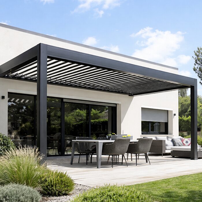
That distinction matters because a pergola connection has to transfer forces into suitable structure without relying on, or damaging, the insulation system. Compressing insulation can leave a bracket poorly supported and harm the façade; choosing a longer fastener by itself does not resolve questions about the substrate, spacing, anchorage or weathering details. Depending on the model and support layout, the wall connection can experience downward force, tension, shear and bending. A projecting frame can also create a lever effect, so the connection is not simply carrying the pergola’s own weight. The stand-off distance and bracket geometry therefore belong in the design too. If you are considering the Bloomcabin Wall-Mounted Pergola, assess the connection for your actual wall rather than relying on the model’s wall-mounted designation.
Identify the structure behind the insulation
Start with records rather than visual guesses. Look for construction or renovation drawings, the external-insulation specification, invoices or installer records, and photographs taken before the finish was applied. Ask the owner, builder or previous insulation contractor what was installed and whether structural mounting points were incorporated. Note additions and later repairs: an extension, infill or patched area may have a different substrate from the rest of the elevation. Do not infer the structure from the house’s age, a brick-looking face or a window reveal; those can conceal a different load-bearing layer. If records conflict with what is visible, record the discrepancy for the site assessor rather than choosing one account.
A competent surveyor or structural professional can compare records with the actual site and decide what further investigation is needed. The assessment should establish the supporting substrate, insulation type and thickness, condition of the proposed fixing zones, and any cavity, frame or reinforced areas relevant to the design. It should distinguish structural backing from facing material or layers that only form the façade. Evidence should cover the intended connection area; one confirmed point does not automatically establish the construction along the whole mounting line. Keep the substrate status as unknown until suitable evidence resolves it; tapping render or guessing from a photograph is not proof. For a particular model such as Bloomcabin Bioclimatic Pergola, request its drawings and compare them with the wall actually surveyed, rather than relying on a detail prepared for another pergola.
Match the pergola load path to the wall
Once the wall build-up is known, map the exact pergola support arrangement onto it. The designer needs model-specific information: the configuration, support locations, brackets or other interfaces, and the reactions the product design assigns to those points. An attractive image or overall dimensions cannot show these values. Wind can act in more than one direction, while the frame’s geometry and projection change how forces reach the wall and any posts. Depending on the arrangement, the structure may need to resist vertical force, tension, shear and bending; any specified additions should be included in the design basis. Reactions depend on the exact configuration, not simply the product family or overall footprint. Do not assume that the wall merely holds the rear edge in place or that posts carry every significant load.
Ask who is responsible for relating the product information to the identified wall and confirming that the connection, substrate and intermediate components work as one system. The supplier should provide information for the chosen model; the site-specific designer assesses whether the real support can receive those reactions; and the installer follows the issued detail. When comparing the Bloomcabin Pergola listing with the supplied drawings, check that the documents name the exact model, its configuration and the support arrangement being assessed. They should also make their design assumptions clear and identify the components included. A detail prepared for a different size or model should not be assumed to apply simply because the products look similar.
Choose a connection designed for the wall build-up
A suitable connection transfers forces across the insulation zone into structural construction by a method designed for that wall build-up. Depending on the substrate and insulation system, a designer may consider a purpose-designed stand-off arrangement or a load-bearing mounting element planned as part of the insulation works. Those options are not interchangeable, and neither is automatically suitable. The detail should show how the bracket is supported, how forces reach the load-bearing layer, and how insulation compression is avoided or controlled. An anchor that suits one backing material may not suit another, even if the outer façade looks the same. The finish must not be asked to bridge a structural gap or serve as an improvised spacer.
Request a connection drawing that identifies the wall construction it assumes, the bracket or interface, the coordinated fixing components, support locations and installation tolerances. It should name any system components rather than say only “fix through insulation”. If the wall is hollow, framed, repaired, unusually thick or not yet identified, the proposal needs to account for that; a generic masonry detail cannot simply be applied. Do not substitute a component because its dimensions appear similar: any change needs agreement from the responsible designer. Use the wall-mounted pergola model page to identify the product when requesting this detail. Ask what substrate evidence and product information support the selected approach, and which changes would require a revised drawing.
What the anchoring drawings should specify
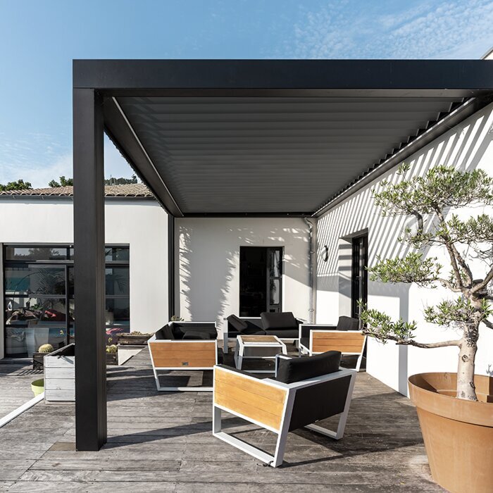
Ask for project-specific, approved anchoring drawings, not just a catalogue image, quotation note or list of possible fixings. They should identify the exact pergola model and configuration, designed support points, substrate type and wall build-up assumed, connection components, and the design information used to select them. The accompanying specification should state the fixing type and installation requirements, including embedment, spacing, edge clearances and permitted tolerances where relevant. These are design outputs, not values for a homeowner or installer to derive by copying a typical detail. Where the fixing manufacturer’s instructions govern installation, the specification should refer to them. Give the drawing an identifiable revision so everyone works from the same version.
The drawing should also clarify how the bracket meets the façade: whether a load-bearing insert or stand-off forms part of the design, how undue insulation compression is avoided, and how the weathering layer is treated. A connection proposal for the Bloomcabin bioclimatic model should state who has reviewed the detail and which wall conditions that review covers. If the actual wall differs, a fixing point moves or the model changes, the design needs review before work proceeds. The drawings and substrate evidence need to agree. Record any approved change in a revised drawing before the connection is covered, so the final documents describe the arrangement that was installed.
Check the proposed fixing positions on the façade
Map proposed connections in relation to the whole façade, not just the pergola frame. Record openings, corners, changes in construction, service routes, vents, downpipes, wall lights and existing attachments; these can restrict fixing positions or conceal pipework and cables. A window reveal, lintel, patched area or visible brick face is not automatically a suitable anchor zone. The survey should note constraints and compare them with the fixing positions in the model drawing. Brackets cannot simply be shifted to a convenient patch unless the revised position and load path are approved for that configuration. Check proposed locations against the areas where access for later inspection will remain possible.
Coordinate the junction with whoever is responsible for the external-insulation finish, especially if the work affects continuity, drainage or existing façade components. The scope should say who designs the interface, who protects or reinstates the finish, and who checks the completed junction; do not assume the pergola installer and insulation contractor have included each other’s work. Note nearby features that shed or collect water as part of the review, rather than leaving their relationship to the connection until installation. For a proposed Bloomcabin Pergola, compare the intended support positions with these façade constraints during the survey; do not leave decisions about moving supports until work begins. Include future access too: if a cover is proposed, the connection should remain inspectable or have a documented maintenance approach.
Protect the insulated façade at the connection
Structural performance is only one part of a wall connection. Any penetration through an insulated façade can create a local thermal bridge; its significance depends on the assembly and connection design. The designer should consider how the detail affects thermal continuity and moisture behaviour rather than treating a bracket as an isolated metal part. The external finish also needs a planned junction so water is not directed behind the insulation or trapped against a vulnerable layer. Existing membranes or cover layers in the proposed area should be identified before the detail is chosen. A bead of sealant applied on site should not be assumed to provide the entire weathering solution.
For a proposed installation of the Bloomcabin wall-mounted model, ask for the weathering and finish detail alongside the anchoring drawing. Confirm that it is compatible with the insulation system and any façade specialist’s instructions. It should explain how the junction is closed, how surface water is managed, and whether future inspection or repair is possible. Existing cracks, loose areas or staining around the intended work should be brought to the professional’s attention rather than simply covered; their cause should not be guessed from appearance. If the drawings say nothing about the outer layers, resolve this before installation instead of leaving an installer to improvise a cover, seal or patch.
When to assess an independent support layout
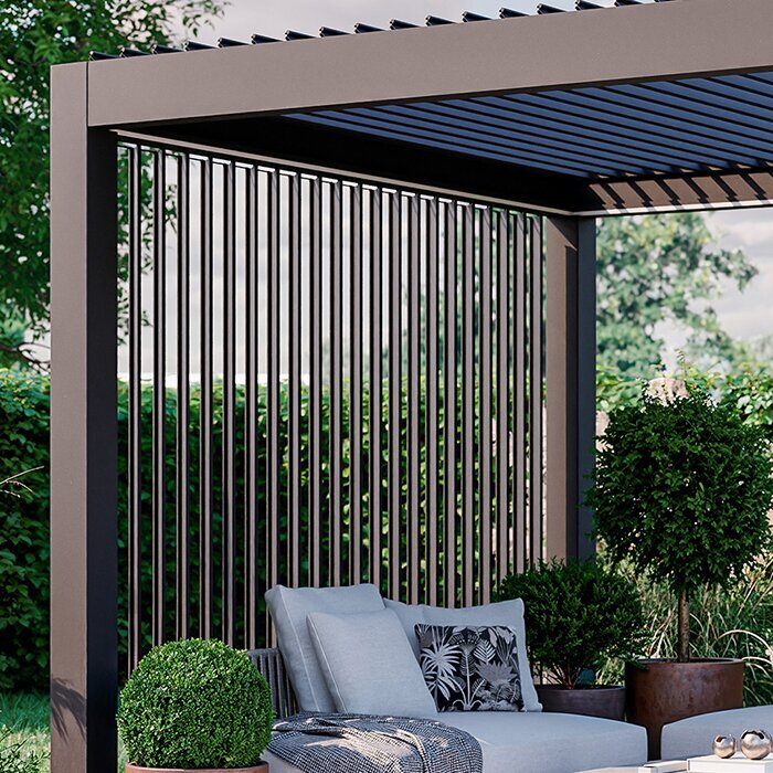
If the structural layer cannot be verified, or a suitable wall connection cannot be designed, ask whether an independent support arrangement is available for the chosen model. This changes rather than removes the load path: posts transfer forces to bases, and those bases need an appropriate design for the actual ground and surface conditions. Existing paving, drainage, buried services, site levels and nearby structures may affect the assessment. A footing size or post spacing cannot be chosen from one generic rule for every terrace. The model drawings must confirm which support arrangements are permitted. If post bases are close to the building or another structure, their relationship should be included in the site assessment rather than assumed to be independent.
An independent frame should not be casually tied back to the insulated wall for stability, nor should a wall fixing be treated as optional if the model’s approved configuration relies on it. Confirm the complete layout with the supplier and site professional before changing from wall-supported to post-supported. The Bloomcabin Pergola model is a way to identify a particular product in that enquiry; its name alone does not show that it is freestanding or can be converted to another support scheme. The relationship between the rear edge and façade still matters for water paths, clearance and future access. Treat an independent layout as a different design to assess, not as an automatic shortcut around the wall question.
Agree who designs, installs and checks the connection
Set responsibilities before ordering materials or booking the installation. The pergola supplier should provide model-specific information and any available support reactions for the chosen configuration. A structural designer or other suitably competent professional should assess whether the identified substrate and proposed connection can receive them. The installer needs a clear issued detail and should raise discrepancies rather than adapt it. Depending on the insulation system, the façade contractor or system provider may need to confirm interface compatibility. Name one person or organisation to coordinate these inputs and the handover between the product, structural and façade details. Put in writing who approves revisions and who must respond if the site differs from the design assumptions.
Keep a concise project record: wall-construction evidence, survey notes and photos, exact model and configuration, approved anchoring drawing, façade weathering detail, and installation or inspection records. This is useful if work changes hands or the connection needs later review; it also shows which wall conditions the design assumed. Before work begins, ask how the actual fixing zone will be checked against the drawing and who to contact if it does not match. An unexpected void, damaged finish or concealed service is a changed site condition, not permission for the installer to select a different fixing on the spot. Record any approved revision with the final documents so the installed work can be compared with the design.
Questions to resolve before installation
Before accepting a proposal, separate three questions: what is behind the insulation; what designed connection transfers this pergola’s forces into that structure; and how will the insulated façade be detailed at the interface? A useful response identifies the wall layers, exact model and support arrangement, project-specific anchoring drawing, and the professional responsible for assessing the connection. “Fixed back to the house” leaves the substrate, load path, fixing components and weathering unresolved. A product image or price quotation is not a substitute for an approved connection detail. If a quote is based on assumptions pending a survey, treat it as provisional until those assumptions are checked.
Ask for unanswered points to be resolved in writing before work starts: evidence for the wall construction, specified components and installation requirements, the façade detail, and what happens if the site does not match the drawing. Clarify whether the wall survey and any further investigation are included in the proposal or are prerequisites. Be cautious if the substrate is guessed from appearance, no one can say who designed the connection, or the only reassurance is that the installer used a similar fixing elsewhere. Similar-looking façades can hide different structures, and the same fixing may not suit a different wall build-up. If the evidence cannot support the proposed connection, reassess the support concept instead of testing a succession of fixings.
Frequently asked questions
Can a pergola be fixed to the render?
Render is a finish, not a dependable structural fixing base. A designed connection needs to transfer the pergola’s forces through the insulation zone to identified supporting construction. The exact detail depends on the wall build-up; a generic anchor suggestion is not evidence that the connection is suitable.
Is a longer screw enough?
No. Length alone does not establish the substrate, required anchorage, bracket spacing, insulation compression or weathering detail. The fixing and any stand-off or load-bearing insert need to be specified together for the exact pergola and verified wall construction.
What if I cannot find drawings for the wall?
Treat the construction as unknown and arrange a site assessment. A competent professional can decide which records, non-destructive checks or appropriately scoped opening-up are needed to identify the supporting wall and insulation system before a connection is designed.
Could posts avoid fixing the pergola to the wall?
Possibly, if the chosen model has an approved independent support arrangement and the ground and bases can be assessed for it. That still requires model drawings and a site-specific review; do not assume a wall-supported layout can simply be converted to posts.
What documents should be ready before installation?
Look for evidence of the wall build-up and condition, the exact pergola configuration, a project-specific anchoring drawing with identified components and installation requirements, a façade weathering detail, and a clear record of who has assessed and approved the connection.
A reliable pergola connection depends on identifying the supporting wall and designing the full junction through the insulation. Establish the façade build-up and substrate, match the exact model’s support information to a designed connection, and coordinate structural and weathering details before installation. If any part remains an assumption, pause the wall-mounted proposal and have the site assessed or the support concept reconsidered. This keeps the pergola’s load path and the protection of the insulated façade within the same coordinated design.
