
Checking Whether a Greenhouse Base Is Square and Level
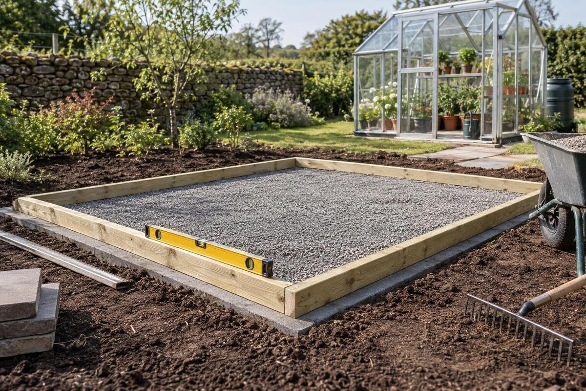
Greenhouse base inspection
A greenhouse base can look level at a few points and still be skewed: its opposite corners may not sit in the intended positions. Levelness and squareness are different checks, and both affect whether the frame can be positioned on its planned footprint without forcing parts into alignment. A reliable inspection uses the drawing for the exact model, measurements from consistent reference points and an installer’s review—not a guessed standard size or a visual check.
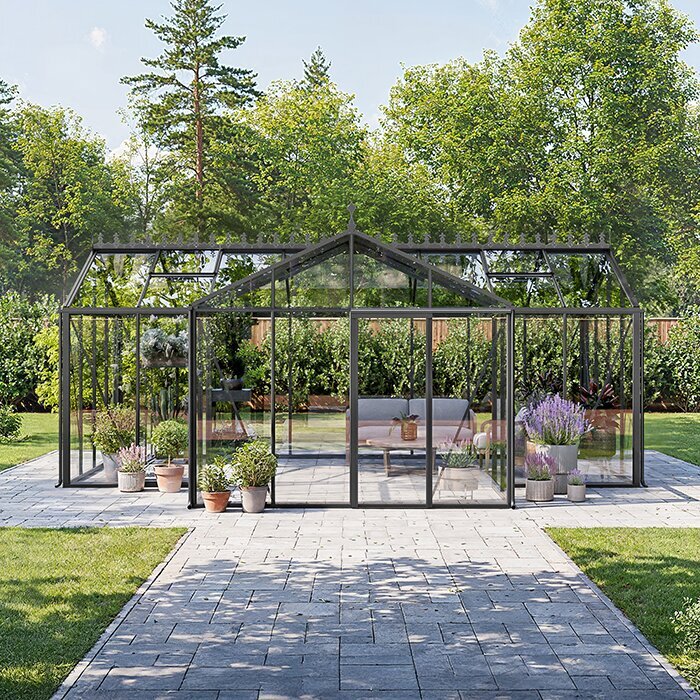
Square and level are separate checks
Level and square describe different properties of a greenhouse base. Level concerns elevation: the relevant bearing points should lie in the horizontal plane specified in the installation instructions. Square concerns the outline and corner angles. For a rectangular footprint, the corners should form right angles and the side lengths should match the drawing. A base intended to be rectangular can be level but skewed into a parallelogram, with corners shifted out of position. Conversely, a base can have the intended rectangular outline but a high corner or a support edge that slopes. A level reading along one edge cannot establish whether the opposite corners are where they should be.
Flatness is a related but separate check. A support edge may read level at its ends but have a local hump or dip between them; a consistently sloped surface can be flat without being level. Inspect the surface that will actually carry the greenhouse base, not a nearby patio or the top of loose soil. The drawing and installer identify which bearing points matter. Consider elevation, local evenness and footprint geometry as separate questions rather than treating one reassuring reading as proof of all three.
Start with the drawing for the exact model
Before measuring, identify the exact model, selected size, configuration and orientation. Find the manufacturer’s base or foundation drawing for the item being installed; a product photograph, catalogue dimensions or a plan for another size is not enough. If you’re planning a Limited-Edition greenhouse with built-in storage, record that exact choice and ask which drawing governs its base set-out. Keep the drawing available to the installer and groundwork crew, and use its labels and revision consistently. Confirm it matches the ordered configuration, including any supplied base component. Do not scale a screenshot or estimate dimensions from an image.
Read what each line on the drawing measures. An outside frame dimension may differ from the footprint or bearing line; a centreline, inside face and outside face are different reference points. Locate the corner marks, dimensions and elevation notes used for base work, and confirm whether a separate base component changes the measurement reference. If the drawing is unclear, ask the manufacturer or installer to identify the points before work is finished. Note that answer on the drawing so one person does not measure to an outside edge while another checks a centreline.
Mark the footprint and keep corner labels consistent
On the drawing, label the intended corners or changes of direction in order—A, B, C and D for a basic rectangle—and transfer those labels to the site. Establish the first reference edge and its position from the agreed layout, then mark the remaining points from the drawing instead of estimating a right angle by eye. For a Prestige greenhouse with a metal base, confirm which line the installer wants checked: the specified base or support line, not an assumed edge inferred from the model name. Use marks or pegs that remain identifiable during the work.
Measure each side between the same defined points used on the drawing. For a rectangular footprint, note all four sides, not just one length and one width; matching diagonals cannot make an outline with incorrect side dimensions match the plan. Keep the corner order visible on a sketch, note the greenhouse orientation, and distinguish a footprint mark from an excavation or paving edge. Write each side as a pair of corner labels, such as A–B, so the record identifies exactly which span was measured. If the drawing distinguishes the entrance side or another reference edge, carry that label onto the sketch as well. This lets the installer connect a reported discrepancy to its location without guessing which side you called the front. Nearby walls, paths and property features are not reliable geometric references unless the installer has confirmed they form part of the approved set-out.
Measure both diagonals, then check the sides
For a rectangular layout, compare the two corner-to-corner diagonals: measure A to C and B to D from the exact corner points shown on the drawing. Keep the tape straight, use the same type of point at each corner and repeat a reading if the tape slips or a mark is uncertain. Equal diagonals are a useful indication that a rectangle is square when its side lengths and corner order also match the plan. They are not a substitute for those checks. If the drawing gives expected diagonal measurements, compare each reading with those figures as well as comparing the two readings with one another.
Measure between consistent reference points—for example, do not take one diagonal between outside faces and the other between centre marks. Write down the readings with the units shown on the drawing rather than rounding them until they appear equal. Keep the A–C and B–D readings on separate lines, and retain any repeat readings beside the originals. If a result changes, note whether a mark was clarified or the tape was repositioned; do not silently replace the first value. That distinction helps the installer understand whether the discrepancy concerns the set-out or an uncertain measurement. A Classic aluminum greenhouse is available in multiple sizes, so use the drawing for the selected size; neither a model-family name nor a remembered measurement supplies its set-out. The installer or manufacturer must confirm acceptable variation for that plan. Do not invent a tolerance because the two results are close.
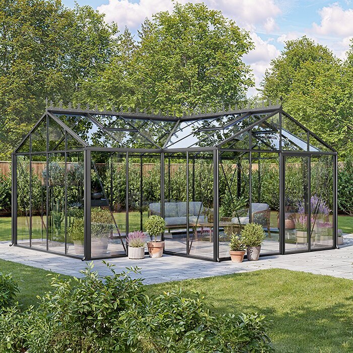
Check level along the actual bearing points
Once the footprint is marked, check elevation along the designated support lines and at the points the installer identifies—not just across one convenient edge. A suitable spirit level or a professional’s laser-level survey can compare points against a common reference. Use the method and datum agreed for this base, and check along the length and across the width, including the corner bearing points. Include any intermediate supports specified on the drawing. Follow the manufacturer’s instructions if they define a particular level reference rather than assuming every visible surface is the one to measure.
Compare readings with the same reference and note where each was taken. A Limited Edition aluminum greenhouse must be checked against its own installation information, not another model’s reference points. Check for twist as well as slope in one direction: corners may appear aligned from one side while other support points sit at different elevations. A straightedge or other suitable tool may help identify a local high or low area, but it does not replace the level check. Record any spot that rocks, dips or prevents the intended bearing for the installer to assess. Mark that location on the sketch rather than describing the whole edge simply as uneven. Keep observations about local surface irregularities separate from elevation readings, so the record shows which issue was found. Where an intermediate point has been checked, label it clearly between the corners so it can be located again after a correction.
Make a measurement record the installer can read
A useful inspection record is a labelled plan plus a measurement table. Write the exact model and selected size at the top, label each point, then record the specified side spans, both diagonals for a rectangular layout and level readings at agreed locations. Include the units, date, person taking the readings and whether the base was complete at the time. Give each measurement its own row, with the drawing reference, specified value where provided, measured value and any relevant comment in separate columns. Leave acceptance decisions to the agreed review rather than labelling a close-looking result as a pass. If a value has not yet been measured, mark it as outstanding instead of leaving an ambiguous blank. For a Spacious Greenhouse selection, record the chosen size: the product family includes multiple area options, so another size’s drawing could give you a misleading comparison.
Take an overview photo showing the full set-out, followed by close views of the measurement points with their labels visible. A photo of a tape alone is hard to interpret if no one can tell which marks or faces it spans. Keep the original readings and annotated drawing together; do not replace them with a note saying only that the base is square or level. If work conceals or changes a reference point after inspection, record the change and ask whether another check is needed. Photos help explain the record but do not establish acceptance by themselves.
How a distorted base can affect assembly
A skewed footprint may make the greenhouse frame difficult to position as shown in the installation information. Rails or corner pieces can meet their fixing points at different distances than expected, and an installer may be tempted to pull components into line. Forcing a frame to meet a distorted base can hide the original discrepancy rather than correct it, making later assembly steps harder to align. The exact effect depends on the model and its connections. Do not alter the structure yourself; have the measured base compared with the intended geometry before assembly continues.
A base that is not at the required level can cause a different alignment problem, even when its footprint is square. Uneven bearing or a sloping support line may leave frame parts out of their intended relationship, complicating the fitting of panels, doors or other moving components. A lean-to greenhouse has its own model-specific layout; do not transfer a freestanding model’s measurements or assumptions to it. Ask the installer to identify the relevant support and reference lines from the approved drawing. Adjusting greenhouse components should not be used to disguise a base error.
Use a different method for shaped footprints
Not every greenhouse outline should be treated as one four-corner rectangle. A T-shaped or otherwise stepped plan has extra corners, offsets or joined sections, and one pair of long diagonals cannot confirm every part. For a T-shaped orangery greenhouse, use the ordered model’s drawing to identify each turn and the dimensions that control it. The product name helps identify the model, but only its drawing establishes where each base segment belongs. Confirm which points the installer will measure, including any junction between sections.
For a shaped footprint, follow the drawing point by point: check each specified segment, the positions of returns or offsets, and any angles or reference lines the plan identifies. The installer may divide the layout into simpler checks, but should explain how those checks together reproduce the complete outline. Do not apply the equal-diagonal test where the drawing does not call for a rectangle. If a detail is missing, ask the manufacturer or qualified installer for a marked set-out. Choosing a convenient diagonal or assuming symmetry can leave one section displaced even if another part looks correct.
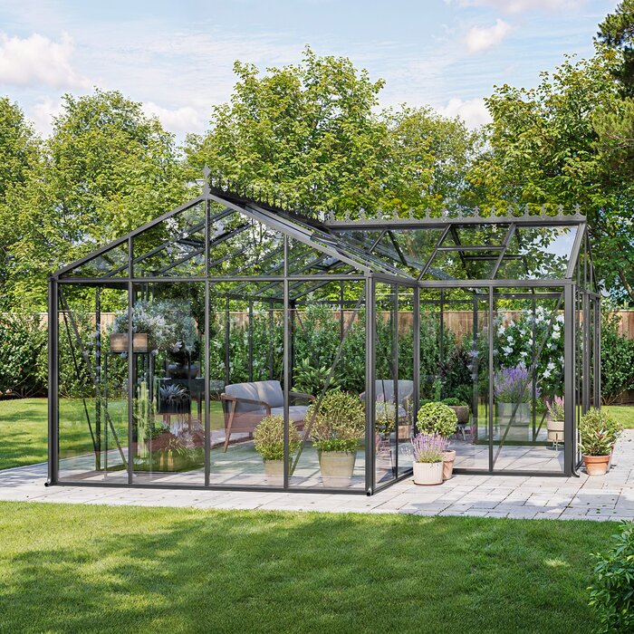
Agree on an inspection hold point with the installer
Agree with the installer on a hold point: a planned pause for inspection before reference marks are concealed or the frame is assembled. Before work begins, confirm the drawing revision, model and size, the exact points or faces to measure, the level reference and how acceptable variation will be determined. Also agree who will take the readings, who will review them and who will tell the crew whether work can continue. Arrange the review while the relevant points remain accessible, rather than discovering at assembly that a needed mark has been covered. The crew can then record the side dimensions, diagonals for a rectangular layout and elevation readings using the agreed method. If the chosen model is a Pyramid Greenhouse, note that clearly so the installer reviews the correct model information rather than a generic sketch. Keep any unresolved measurement questions visible in the record for that review.
At the hold point, the installer reviews the measurements against the specified plan and acceptance criteria, checks that the photos match the labelled points, and records whether the base can proceed to assembly. If the plan gives no tolerance or the readings conflict, ask the installer to seek clarification from the manufacturer rather than declare a pass by eye. A clear record includes the drawing revision, labelled side and diagonal values, level readings and locations, photos, discrepancies and the installer’s decision. This is an example of a process to agree—not a universal numerical standard.
What to do when measurements do not match the plan
If the checks do not agree, pause before fitting the greenhouse. Confirm that you used the correct drawing, units, corner order and measurement faces, then repeat any uncertain reading with the same reference points. Give the record to the installer and ask which measurement controls the correction. The right remedy depends on the base type, what is out of position and the installation requirements. Do not move a frame to hide the discrepancy, trim parts or add improvised packing unless the installer or manufacturer has approved that approach for the specific design.
After a correction, repeat the affected geometry and level checks, not just the one value that initially looked wrong. Ask the installer to record the revised readings and confirm that the hold point has been released. Keep the revised results alongside the earlier record, with a brief note identifying what was corrected and when. This preserves a clear account of the work without making readers reconstruct it from separate messages or photographs. If the base meets the agreed criteria but a component still will not align during assembly, stop and compare the installed base, supplied model and instructions before applying force; more than one issue could be involved. A complete record makes the discussion concrete and keeps decisions about groundwork and assembly with the people responsible for them.
Frequently asked questions
Can a greenhouse base be level but not square?
Yes. A base can sit at the required elevation and still have corners out of position, leaving its outline skewed. Level readings check elevation; side measurements and diagonal comparisons help check a rectangular footprint. Compare both kinds of results with the drawing for the greenhouse being installed.
How do I check whether a rectangular base is square?
Mark the four corners shown on the drawing, measure both diagonals between opposite corners from the same reference points, and compare the results. Also check every side against the specified lengths. Equal diagonals are a useful cross-check, not a substitute for confirming the footprint dimensions.
Do equal diagonal measurements prove the base is square?
Not on their own. Equal diagonals can be a useful check for a rectangular layout, but they do not prove that the base has the intended side lengths or outline. For a shaped footprint, a single pair of diagonals may not apply at all. Follow the drawing's specified points and checks.
How level does the greenhouse base need to be?
Use the level requirements and acceptance criteria for the exact greenhouse and base arrangement. If they are not clear, ask the installer or manufacturer to define them before assembly. There is no universal tolerance to substitute for the requirements of the specific plan.
What should I do if the diagonals differ?
Confirm that you used the correct drawing, corner points, measurement faces and units, then repeat any uncertain reading. If the difference remains, pause before assembly and ask the installer to assess it against the plan. Do not pull the frame into position or make an improvised correction.
A dependable handover rests on three separate results: the specified sides and corners are in position, both diagonals have been checked where the plan is rectangular, and the bearing points meet the required level. One result cannot stand in for the others. When the installer has reviewed the measurements against the correct drawing, the base’s condition is documented before greenhouse assembly begins.
