
Why a Greenhouse Base Needs to Be Square and Level
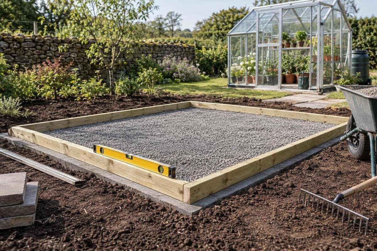
Greenhouse groundwork
A greenhouse base has two separate checks: it must sit at the level required by the manufacturer’s installation drawing, and its footprint must match the intended geometry. A surface can read level while its corners are skewed; a correctly set-out rectangle can still have a low edge. Either mismatch can complicate frame alignment and openings. Comparing diagonals is a useful way to spot a problem, provided the measuring points and acceptable tolerance are agreed against the actual model drawing.
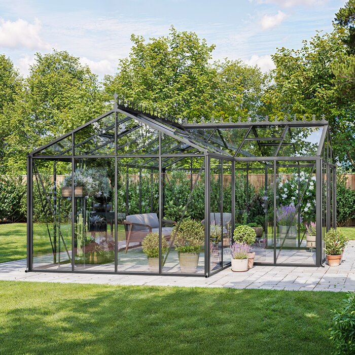
Level and square are separate requirements
When a greenhouse base is described as square, the word usually means its corners are square: the sides meet at right angles and the outline matches the drawing. It does not mean every side has the same length. A rectangular base can be square-cornered even when it is longer in one direction. This distinction matters because measuring only one pair of sides, or assuming that a balanced-looking layout is literally a square, can give a misleading impression of the layout. If the drawing shows returns, bays or another non-rectangular outline, use its defined lines and corner positions rather than treating the whole perimeter as one rectangle.
Level describes vertical position. The relevant support points should lie in the level plane required by the manufacturer’s installation information. This is different from flatness: a surface can be level between two reference points yet have a local ridge, while an even surface can still be inclined. Neither property confirms that the corners form a rectangle. Four corners could share one height but be skewed in plan; a square-cornered outline could have a low edge. Take plan measurements and elevation readings as separate checks, including any intermediate support points shown on the drawing, rather than relying on one bubble reading or a visual judgement.
What levelness means for the base
A level check concerns the height of the points where the greenhouse base or its specified supports bear. Use the points identified by the manufacturer’s drawing, rather than checking only the centre of the floor or a convenient part of the surface. One reading in a single direction cannot establish the level across the whole footprint. Nor does a smooth-looking surface show that distant corners share the required elevation. If the plan specifies several support lines or points, include them in the inspection. The relevant reference and acceptable variation should come from the model information and the installer, not from a general assumption about the base.
Elevation matters because frame members are assembled against a common reference. If one support point is high or low, parts may not sit evenly, and joints, panels or doors can be harder to align, depending on the design. This is not a reason to force parts into position during assembly. When setting out an Aluminium Classic Greenhouse, identify the exact selected size and use its matching manufacturer information; the product-family name alone does not state where to take readings or what height variation is acceptable. Agree the reference points with the installer before treating the base as ready.
How a skewed footprint can affect assembly
An out-of-square footprint has sides or corners that do not match the intended plan. The error may be hard to see: the perimeter can look neat while one corner has moved and the side positions no longer correspond to the drawing. During assembly, a rail may reach a corner before the adjoining side is in its intended position. Frame joints or fixing points can then be difficult to align, and there may be a temptation to pull the structure into shape. That can hide the setting-out error rather than resolve it, making it harder to identify the actual cause of a poor fit.
Depending on the design, a distorted outline can also leave openings uneven or prevent panels and seals from fitting properly. These are possible consequences, not a guarantee that every small mismatch will cause a visible problem; the model information and installer’s tolerance matter. When choosing the Bloomcabin Prestige Greenhouse with metal foundation, remember that the supplied foundation does not establish whether the prepared site outline is square or positioned correctly. Check the exact drawing and intended fixing lines for your selected size. If parts resist alignment, pause and ask the installer to inspect the base instead of applying force. Measurements make it easier to distinguish a base issue from an assembly issue.
How to compare the two diagonals
For a four-corner rectangular plan, label the corners in order A, B, C and D using the drawing, then compare A-to-C with B-to-D. Use the exact points defined by the drawing or installer, such as a specified edge or centreline, rather than whichever point is easiest to reach. Keep the measuring method consistent, record both results in the same units and repeat any reading that was interrupted or taken from an uncertain mark. If the base has different elevations, or its corners are not clearly marked, ask the installer how to measure the distances in plan; a tape stretched over an uneven surface may not represent the intended layout.
The two diagonals of a rectangle should match within the agreed tolerance, so a difference is a prompt to investigate. It does not show by itself which side has moved or what correction is needed. Equal diagonal lengths alone do not prove that every four-sided outline is rectangular; other shapes can also have equal diagonals. Check the side dimensions and the right-angle or control-line information in the drawing as well. For a non-rectangular model, use its defined points instead of relying on the outermost diagonal pair. There is no universal pass figure to insert here: compare the recorded measurements with the model-specific criterion agreed with the qualified installer.

The drawing, not the floor area, sets out the base
The manufacturer’s base drawing turns a product choice into a measurable layout. It should identify the relevant perimeter, support positions, fixing points and any relationship with a wall or other boundary. Use the drawing for the exact model and size, not a similar greenhouse image or measurements borrowed from another variant. Check which line each dimension refers to: an outside edge and a centreline are not interchangeable. If two documents appear to use different references, resolve that before marking out. Keep the drawing version with the inspection notes so that everyone involved is comparing the base with the same plan.
Floor area is easy to mistake for a set of dimensions. The Spacious Greenhouse range is listed from 47 to 70 m², but an area figure does not give you the selected option’s length, width, corner positions or diagonal. Different proportions can produce a similar area, and a shaped footprint needs more detail than area alone. Confirm the dimensions for the exact item and obtain its manufacturer drawing before accepting the set-out. A product page can help identify the model, but it does not replace the information needed to lay out the base or a review of the actual site by the installer.
Wall-mounted and irregular plans need tailored checks
A wall greenhouse needs careful checking where its base meets the building. The wall may look like a straight reference, but that does not establish that the base line is square to it, level or positioned at the angle required by the greenhouse drawing. For a Wall Greenhouse, use the manufacturer’s plan to identify the wall-side line, opposite edge and specified fixing points; have the installer check the relationship on site. Do not set out from a convenient building corner unless the drawing and installer confirm that it is the correct reference. A wall-side measurement should not replace the other checks.
Some plans include returns, projections or more than one rectangular bay. One pair of diagonals across the whole outline may not show which part is out of line, and may not be a meaningful rectangle test at all. The drawing may define separate rectangles, parallel reference lines or control points; inspect those features individually. Do not use a model name or a symmetric-looking photograph as proof of the base geometry. If the plan does not make the measurement points clear, ask the manufacturer or installer to identify them before groundwork proceeds. That prevents a visually plausible set-out from being mistaken for the specified one.
Agreeing a base inspection with the installer
Agree the inspection method with the installer before anyone takes measurements. For example, before assembling a Pyramid Greenhouse, first confirm from its actual manufacturer’s drawing whether the base is a simple rectangle or has another outline. Then agree which corners or control points to use, where to take level readings, which edge each dimension follows and what tolerance applies. Do not infer the base shape from the word ‘Pyramid’ or from a product image. The purpose of this example is to check the model’s set-out, not to assume a particular geometry from its appearance.
At the inspection, the installer and groundworker can mark the drawing-defined points on the base, record the relevant level readings and measure both diagonals if the drawing shows a rectangle. They can also compare the side dimensions or other control lines. The record should identify the model, drawing version, measurement points, date and agreed criterion, as well as whether the result meets it. If a figure falls outside that criterion, note the location and pause frame assembly while the installer decides what to examine. Dated photographs with labelled points can help explain the record, but they do not replace measurements. This outline describes what to agree in advance; it does not establish a universal inspection method or tolerance.
Investigate a mismatch before altering the base
A different diagonal reading can indicate a genuine layout error, but first check that the two measurements used comparable points. Confirm that both run from the same type of corner reference, that the tape was held consistently and that the marks have not moved. Do not measure one diagonal to an outside edge and the other to a centreline. Then compare the side measurements and level readings with the drawing. A square perimeter does not guarantee that a separate support or fixing line is in the right position, so inspect the actual reference used by the frame. Record what you find before changing any marks.
For the Limited Edition aluminium greenhouse with built-in storage, use the drawing for the selected configuration to establish which edges and supports form part of the base set-out; the storage description alone does not define them. If a discrepancy remains, give the measurements and photographs to the installer or a qualified groundwork professional and ask for a remedy that preserves the specified layout. Avoid forcing the frame, widening holes or adding improvised packing unless the responsible professional confirms the approach. A careful recheck can reveal a measuring error, but a persistent mismatch needs a considered correction rather than a guess.
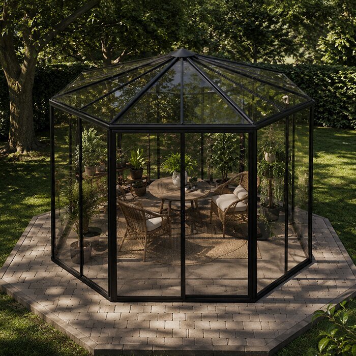
A model or size change calls for a fresh check
Once a base has been laid out or inspected, a change to the greenhouse size, orientation or model should prompt a fresh comparison with the manufacturer’s drawing. A different size can shift the sides and diagonals even if it belongs to the same product family. Turning a plan can also change its relationship to a wall, access route or prepared services. Do not rely on the earlier set-out because the new choice looks similar. Tell the installer what has changed and ask which dimensions, support lines or control points need to be checked before accepting the base.
The Limited Edition Aluminium Greenhouses range is listed from 3.77 to 28.08 m²; that area range is not one shared base plan. An earlier measurement remains useful only if it refers to the exact same configuration and drawing. Mark any new corners separately from old lines and label the readings so they cannot be confused. If the revised plan changes a support position or overall outline, ask the installer whether the prepared base still matches. A diagonal recorded for the previous plan is not evidence that the changed model will fit.
Record the result before frame assembly
Make the inspection record clear enough for the installer to use at handover. Include the exact model and size, drawing version, points measured, side or control-line dimensions, both diagonals where appropriate, level readings and the agreed tolerance. Record any correction and the readings taken afterwards; a result from before the correction does not confirm the revised base. Keep the notes with the drawing and ensure that everyone involved is using the same version. If part of the set-out remains unverified, state that plainly instead of treating a visual check as sign-off.
If the drawing for a T-Model Orangery Greenhouse defines several bays or control lines, name each one in the record. A single diagonal pair cannot document every part of a multi-section outline. Ask the installer to confirm which checks have passed and whether anything still needs attention before the greenhouse frame is assembled. This is not paperwork for its own sake: a labelled record helps the next person measure the same lines and prevents a corrected level reading from being mistaken for proof that the base is also square.
Frequently asked questions
Can a greenhouse base be level but out of square?
Yes. Levelness concerns height; squareness concerns the footprint in plan. A base can have its measured points at the required level while its corners do not match the intended right angles. Check both separately against the drawing.
Do matching diagonal measurements prove that a base is square?
No. Matching diagonals are a useful check for a rectangular footprint, but equal lengths alone do not prove that every four-sided outline is a rectangle. Also check the side dimensions and the drawing’s corner or control-line information.
Where should I measure the diagonals from?
Use the exact corner points defined by the manufacturer’s drawing or agreed with the installer. For example, do not measure one diagonal from an outside edge and the other from a centreline. If the points are unclear, ask the installer to mark them.
How much difference between the diagonals is acceptable?
There is no universal tolerance that suits every model and base arrangement. Ask the installer to confirm the acceptable variation against the drawing for your exact greenhouse. Do not use an assumed figure or judge the result only by eye.
Should the frame be pulled into place if it does not align?
Pause and have the installer check the base and measurements before trying to fit the frame by force. A mismatch may come from the set-out, the reference points or another issue; the installer can identify what needs attention before assembly continues.
A base that is level but skewed, or square-cornered but uneven, has not passed both checks. When the model drawing, diagonal comparison, side or control-line measurements and elevation readings agree within the installer-approved criteria, the frame can be assembled from a known reference rather than forced to absorb an error. That is the value of checking the layout before assembly.
