
A Level Greenhouse Base Can Still Be Out of Square
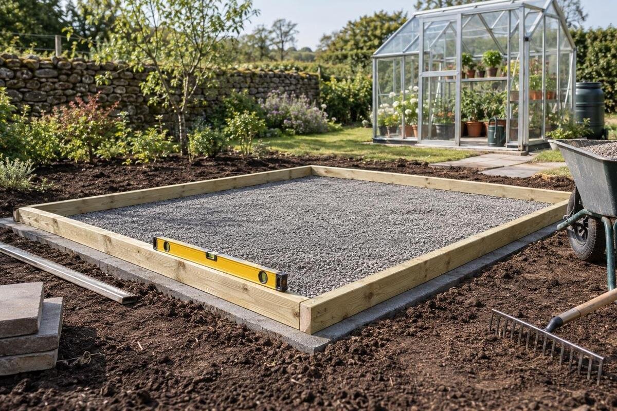
Greenhouse groundwork
Before a greenhouse frame goes together, checking that the base is level is not enough. Level describes height; square describes the footprint’s geometry. Those are separate checks, and one cannot stand in for the other. This guide explains what diagonal measurements can reveal, where they can mislead and what to agree with an installer before assembly begins.
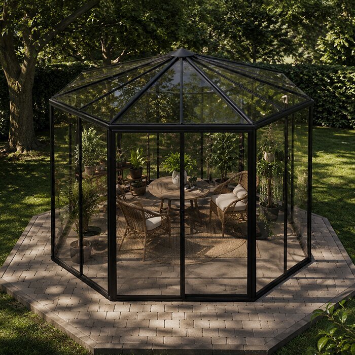
Level and square are separate checks
Level concerns elevation: the specified points on the base sit at the required height relative to a horizontal reference. Square concerns the outline seen from above: its sides meet at the intended angles. In setting-out, a rectangular base is considered square when its corners are at right angles; its length and width do not have to be equal. A base can therefore be level around its perimeter but skewed in plan, or correctly shaped in plan yet tilted or uneven in height. If you are planning for a Classic aluminium greenhouse, use the drawing for that exact model rather than borrowing a layout from another greenhouse.
Think of these as two independent tests. Moving one corner sideways without changing its height can distort the outline while leaving the base level. Conversely, a frame with right-angled corners can sit on a base with a high or low point. A reading taken at one place tells you about that location, not the geometry of the whole footprint. A single length measurement does not establish the angles either. Before assembly, confirm the intended dimensions and plan shape as well as the required level; one check cannot stand in for the other.
Use the exact model drawing to choose measurement points
Start with a plan or base drawing for the greenhouse you actually intend to install. It should be clear which outline and dimensions apply, and where the relevant reference points are. A drawing may refer to the outside edge of a base, a frame line or fixing locations; those are not interchangeable measuring points. If the drawing does not make the reference clear, ask the manufacturer or installer to identify it before setting out. A catalogue image, a nominal width and depth, or a drawing for a similar-looking greenhouse is not a reliable substitute.
Record the full model name and chosen configuration when requesting the setting-out information for a Limited-Edition Aluminium Greenhouse with Built-In Storage. Do not assume that a drawing for another model or configuration gives the right base points. Check the drawing’s orientation too, so the entrance end and any returns face the same way on the plan and on site. Identify which marked line represents the support being measured: a dimension taken between frame reference points should not be compared with a reading between unrelated paving edges. If documents use different units or show more than one outline, have the installer confirm which dimensions govern before any permanent work proceeds. Keep those reference points clearly labelled on the working plan so everyone checking the base measures the same thing.
What diagonal measurements can reveal
For a four-corner rectangular footprint, label the drawing’s specified points A, B, C and D in order around the perimeter. Measure from A to C, then from B to D, using the same kind of reference point at each end. Keep the tape straight across the plan rather than following the perimeter, and have someone hold the far end if needed. Take care that the tape does not pull a marker out of place. Before recording a reading, agree exactly where the tape starts and where its scale is read at the opposite point. Measuring to the near edge of one mark and the far edge of another makes the comparison unclear. Record both readings with their endpoint labels, rather than simply writing ‘diagonal one’ and ‘diagonal two’. Another person should be able to repeat the measurements without guessing which corners or edges you used.
A true rectangle has equal diagonals, so different readings are a warning that the intended rectangle may be skewed or that the wrong points were measured. Recheck the marks before drawing a conclusion. Equal readings are useful but do not prove that every four-sided outline is a rectangle: other shapes can have matching diagonals. Compare the side dimensions and corner positions with the drawing as well, and use the manufacturer’s stated tolerance rather than inventing one. If your paperwork names a Bloomcabin Prestige Greenhouse, use the drawing for that exact model instead of applying a generic greenhouse dimension.
An example of checking a rectangular base
Consider an inspection for a Spacious Greenhouse where the relevant model drawing shows a four-corner rectangular base. The example here illustrates the checking process; it is not a record of an approved installation. Ask the installer to confirm the measurement points and acceptance criteria first. Label the specified points A to D, measure each side and both diagonals, and take level readings at the locations identified on the drawing. Keep the plan measurements and height readings in separate parts of the record so they cannot be confused. The installer can then compare each result with the corresponding model-specific dimension or stated tolerance. This separates three questions: whether the base has the intended length and width, whether its outline is square, and whether its support is level.
Suppose the four reference points meet the level criteria, but the two diagonals differ. That result does not contradict the level readings: it identifies a separate question about the plan shape. The installer should first confirm that the tape started and ended at the correct points, then repeat the measurements and compare the side lengths with the drawing. Record the actual readings rather than summarising the base as ‘nearly square’, which leaves the discrepancy undefined. If the difference remains, hold assembly while the installer or manufacturer agrees what must be corrected. After any agreed correction, repeat the same checks, including level rather than only the diagonals. The example does not establish a universal dimension or tolerance, and the inspection method is suitable for the actual project only when the installer confirms its reference points and criteria.
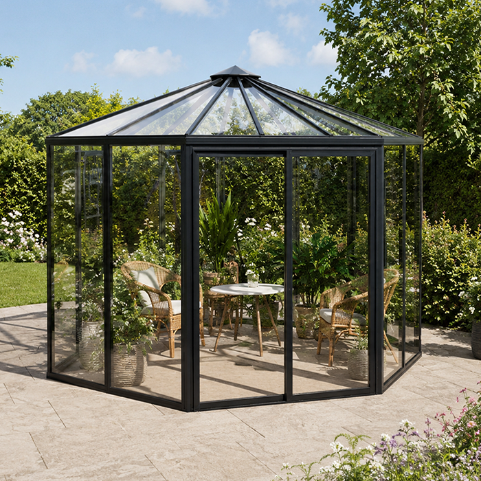
Check level across the support surface
Take level readings at the points and along the support lines specified for the base, rather than relying on a single reading near the centre. Include corners and intermediate points where the installer’s method calls for them. A short spirit level can show a local difference, but the appropriate instrument and method for checking a full run depend on the job. Ask the installer to explain the reference used and how readings from different parts of the base are compared. Note each reading beside its location on the plan; a list of heights without locations cannot show which part of the support needs attention. Keep this record distinct from the diagonal measurements. A diagonal is a plan measurement between opposite reference points, not a substitute for checking whether one corner or support section sits higher than another.
Level and flatness are related but not identical. A surface can be even along its length yet slope overall; readings at the corners can also miss a raised or dipped section between them. Check the actual support surface, not just its outline. If the chosen product is a Lean-to Greenhouse, do not assume that an adjoining wall or nearby paving proves the base is level or correctly set out. Use the model drawing and the installer’s specified reference points, and ask before making up a height difference with packing or another unapproved adjustment.
How a distorted base can affect assembly
A frame is made to fit a particular footprint. If the base is skewed, corner members may not meet where expected, holes or fixing points may not line up, and rails can be difficult to position without pulling them sideways. A small-looking difference on the ground can become apparent when the frame is joined across its full width or length. The result may also affect how glazing sits or how an opening operates. These are possible alignment problems, not proof that every discrepancy will cause the same fault; the model’s instructions and an installer’s assessment determine what matters for that frame.
If components resist the intended fit, pause rather than using the frame to force the base into shape. Tightening parts to draw them together may hide the original discrepancy while leaving the assembly under strain. For a Limited Edition Aluminium Greenhouse, consult the instructions and base drawing for the selected configuration before changing the assembly sequence. Describe where the fit becomes difficult: at a corner connection, along a rail or at a fixing point. That gives the installer a clearer starting point than saying the whole frame is wrong. Recheck the relevant base measurements and reference points, then let the installer assess whether the groundwork needs attention. Resistance during assembly is a reason to investigate, not permission to alter parts or pull the base into alignment.
Use a different method for shaped footprints
The two-diagonal check is intended for a four-sided rectangular outline. It is not a complete test for a multi-sided, T-shaped or otherwise irregular plan. A shaped footprint has more corners and changes of direction to account for; checking just one pair of cross-measurements can leave another section incorrectly positioned. Use the dimensions and reference points shown for the full outline, including internal corners or projections where the drawing specifies them. Do not assume that the entire plan can be verified by treating it as one rectangle.
For a T-Shaped Orangery Greenhouse, check the actual outline rather than assuming every greenhouse has a simple rectangular base. Ask the installer which points and measurements should be recorded for that shape, and whether separate sections share a reference line. Label the junctions and changes of direction on the working drawing so a measurement cannot be mistaken for one taken across the whole footprint. If the drawing is unclear about a junction or angle, have it explained before marking the ground. Dividing a complex shape into smaller rectangles may help describe the plan, but it does not by itself confirm that their shared lines or meeting points are correct. The inspection needs to show both the shape of each relevant section and its position within the complete outline, using the relationships specified on the drawing.
Check the finished base, whatever its construction
The material used for a base does not determine whether its outline is square or its surface is level. Concrete, paving and a purpose-designed base system each still need to match the footprint and support requirements shown for the selected greenhouse. A straight-looking edge can be in the wrong place, and a level surface can still have an incorrect plan shape. Do not choose or alter a foundation arrangement from a generic dimension; the manufacturer’s drawing and a qualified groundwork review are the references for the actual project.
Agree when the setting-out measurements will be checked and when the completed support will be inspected. These are distinct stages: marks show the intended position, while the finished base is what the frame will sit on. For a Pyramid Greenhouse, use the plan for the exact choice at both stages rather than relying on the model name to establish the outline. If a boundary or the site layout prompts a change to the drawn position or shape, refer it to the installer before proceeding. Keep the agreed reference points identifiable through the work so the final inspection can use the same measurement basis. Before assembly, compare the completed support with the drawing and resolve any mismatch; an earlier check of the setting-out marks is not a record of the finished base.
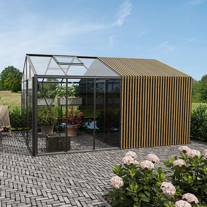
What to do when measurements do not agree
If the diagonals differ or a level reading falls outside the stated criteria, repeat the measurement before changing the base. Confirm that the marks have not moved, that the tape begins and ends at the specified points, and that the correct drawing is being used. Then check the side lengths and the relevant level readings. A discrepancy may come from a measurement error, a wrongly positioned marker or the base itself; a single result does not identify which. Keep the readings separate rather than adjusting one value to make the set appear consistent.
If a careful recheck still conflicts with the drawing, ask the installer or groundwork contractor to assess the issue before assembly. Explain whether the unresolved result concerns a side dimension, a diagonal comparison or a level reading, and identify the affected points. Agree who will decide on a correction, who will carry it out and which measurements will establish that it is complete. Keep a measurement query separate from an agreed repair: recording a difference does not, on its own, identify the right adjustment. Avoid cutting, packing or moving part of a completed base on guesswork, and do not use the greenhouse frame to test whether the discrepancy can be pulled out during assembly. Once an agreed adjustment is complete, repeat the relevant measurements before continuing.
Record the inspection before assembly
Keep a simple inspection record that another person can follow. Note the model and configuration, identify the drawing used, and label the reference points consistently on a copy of the plan. For a rectangular outline, pair each side and diagonal reading with its endpoint labels; record level readings beside their specified locations. Include the units so a figure is not left open to interpretation. Photographs can show where a tape or measuring instrument was placed, but they work best alongside written readings and the marked drawing. If a measurement was repeated or a point was corrected, distinguish the original observation from the final result and note what changed. Do not leave several unlabelled figures beside the same dimension. The record should make clear what was measured, which result was accepted and whether it describes the original setting-out or the completed base.
Before the frame goes together, ask the installer to confirm that the base has been checked for both plan geometry and level, that the applicable criteria come from the correct model information, and that any discrepancy has been resolved. If the acceptance tolerance is not shown in the paperwork, ask who will confirm it rather than relying on an assumed general rule. A clear record makes it easier to distinguish a level issue from a shape issue and gives the installer a specific basis for deciding whether the base is ready.
Frequently asked questions
If the base is level, is it automatically square?
No. Level describes height relative to a horizontal reference; square describes the footprint’s angles. A base can be level at every corner and still be skewed in plan. Check both properties separately against the drawing for the exact greenhouse.
Do matching diagonal measurements prove that a base is square?
Not on their own. Equal diagonals are expected for a rectangle, but other four-sided shapes can also have equal diagonals. Confirm the measurement points and check the side dimensions and angles required by the model drawing.
What difference between the diagonals is acceptable?
There is no single tolerance that applies to every greenhouse and base arrangement. Ask the manufacturer or installer to identify the acceptable criteria for the exact model and drawing. Do not treat a generic figure as approval.
Can I use the greenhouse frame to pull the base into shape?
Do not rely on the frame or its fixings to correct a base that does not match the drawing. Forcing parts into alignment can complicate assembly or put unwanted strain on the frame. Pause and ask the installer to assess the discrepancy.
Do diagonal checks work for a T-shaped or multi-sided footprint?
Not as a simple two-diagonal test. Use the reference points, dimensions and angles shown for that specific outline. Ask the installer which cross-measurements are relevant; do not reduce a complex plan to one rectangle unless the installer confirms that method.
A sound base check looks at the footprint from above and its height across the support, using the drawing for the exact greenhouse. Diagonals are useful for a rectangular plan, but they are only part of the assessment. When an installer has confirmed the relevant measurements and resolved any mismatch before assembly, the frame can be fitted to a base that has been checked for both shape and level.
