



Electrical planning for a motorised pergola: louvres, controls and lighting
A motorised pergola should be planned electrically as part of the whole site. This guide explains what must be confirmed before cables are installed, how supply and control wiring can be coordinated, and what to consider for lighting, commissioning and later additions.
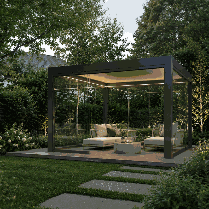
For a motorised pergola, the structure, foundations, drainage and electrical equipment form one planning system. If cable routes are decided only after installation, visible cables, unnecessary drilling or difficult-to-reach connection points often result. Early coordination between the owner, pergola installer and licensed electrical professional reduces these risks.
This guide covers planning steps. It does not replace the specific model’s technical documentation or work by a qualified electrical professional. Connection data, protective measures and local requirements must always be confirmed for the project.
Which parts of a motorised pergola need power?
The most obvious load is the louvred-roof drive. Depending on the system, a controller, receiver, power supply, wall switch, integrated lights or optional sensors may also need power. Remote controls usually operate independently of the fixed installation, but require a compatible receiver at the pergola.
Not every bioclimatic pergola has the same electrical architecture. A motor may operate directly from mains supply, through a separate power supply or through a manufacturer-specific control unit. Voltage, cable type and connection method must therefore never be assumed from external appearance.
- Louvre drive: moves the roof louvres and needs a clearly allocated supply.
- Controls: process signals from switches, remote controls or compatible sensors.
- Lighting: may be integrated, surface-mounted or installed independently of the pergola.
- Optional equipment: for example sensors or later side solutions with electrical components.
Details that must be confirmed before electrical rough-in work
Before chasing, drilling or laying underground cable, the exact pergola model must be selected. The guides to choosing between bioclimatic and classic pergolas, to wall-mounted or freestanding installation and to pergola sizing help clarify the structural basics first.
| Information required | Why it matters |
|---|---|
| Exact model and specification | Determines the motor, controls, possible lights and intended connection positions. |
| Orientation and post positions | Determines where cables can emerge without obstructing foundations or drainage. |
| Motor and control side | Prevents the supply cable being prepared at the wrong end. |
| Electrical manufacturer documentation | Contains the binding connection and compatibility information. |
| Preferred control locations | Affects cable routes for switches, controls and, where needed, extra switching points. |
| Lighting and expansion plans | Allows sensible provision without fitting unused equipment. |
The planned pergola range and its current installation manual must also be clearly identified. Product images or general sketches are not sufficient for electrical rough-in work.

Plan the pergola and electrical work as one site system
A cable plan should use the same dimensioned site drawing as the foundation and installation plans. It should show the building connection, pergola axes, posts, foundation blocks, patio build-up, drainage direction, cable routes and exit points together. The guide to pergola foundations explains why the substructure should be resolved before installation.
Cables must neither obstruct fixing areas nor emerge uncontrolled where water drains from the roof system. A conduit should not end where it could be crushed while a post is placed or struck by fixings. Existing patios also require consideration of build-up height, waterproofing and possible movement joints.
Before building work begins, also check whether local requirements apply to the project. The guide to pergola consent requirements in New Zealand is an initial overview; check the specific site and intended use with the relevant council.
Electrical cable routes for freestanding and wall-mounted pergolas
Freestanding pergola
For a freestanding structure, the supply cable often runs underground to a predetermined post. The electrical professional must set the route, installation depth, mechanical protection, cable type and entry method for the site. Conduit is useful only when its dimensions, bend radii, sealing and final position suit the intended cable.
The cable exit must match the installation drawing exactly. A broadly estimated point within the foundation area may later sit directly beneath a base plate or outside the post profile. The page on the freestanding Bloomcabin pergola provides guidance on this format.
Wall-mounted pergola
For a wall-mounted pergola the supply may come from the building. Even so, the shortest cable route is not automatically best. Insulation, wall construction, waterproofing, loadbearing elements and wall-fixing locations must be considered. Wall penetrations must be professionally sealed against moisture.
Before routing the cable, confirm on which side the motor or controls are located. The specific wall-mounted pergola configuration is decisive. A cable should not be positioned from a perspective product image alone.
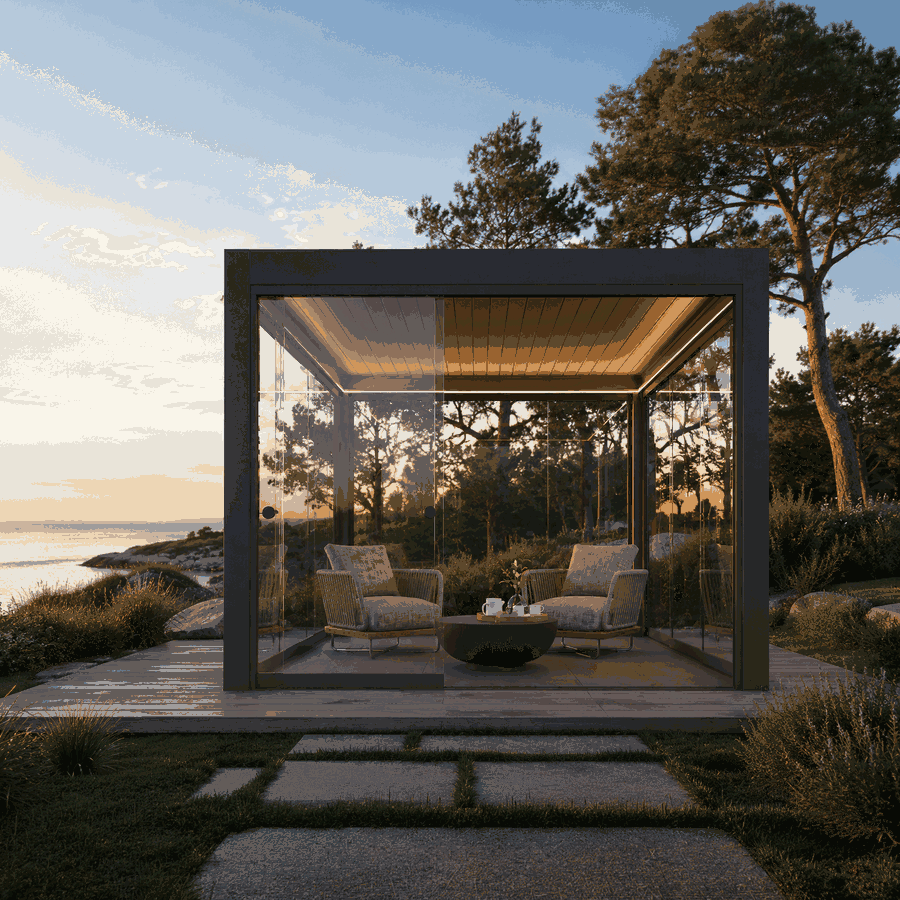
Plan the power supply and circuit
An electrical professional assesses load, cable length, installation method, environment, protection and the existing switchboard. These determine cable size, overcurrent and residual-current protection, and whether a dedicated circuit is useful or required. Generic figures are unsuitable because models, accessories and building installations vary.
Motor and lighting can technically be supplied together or separately if the product documentation and professional design allow it. Separate circuits or independently switched feeds can simplify fault-finding: a lighting fault does not then necessarily stop the roof drive. However, an unnecessarily complex installation should not be created without a specific benefit.
An existing outdoor socket is not automatic proof of a suitable supply. Its condition, protective measures, loading and circuit allocation must be checked. Temporary extension leads are not a substitute for a permanently planned outdoor installation.
Keep mains and control wiring properly separated
Cables carrying different voltages and signal types must not be run or connected together without consideration. Required separation, enclosures and cable types depend on the particular system and applicable rules. Improvised transitions between manufacturer-specific motor cables and the building installation are especially critical.
Label every cable clearly and permanently at both ends. Also photograph open routes and mark reference points on a plan. If conduits end at several posts, label each one. A draw wire helps with later work but does not replace checking that the route is usable.
Location of louvre motor and controls
The motor, junction box and control unit must remain accessible without being permanently visible or unprotected. Maintenance access does not mean components must be exposed without tools. It means a professional can reach them without unnecessarily dismantling structural parts, roof louvres or fixed linings.
Controls should be installed only in an orientation and environment approved by the manufacturer. Water paths, condensation, direct weather exposure and heat build-up must be considered. For a motorised Bloomcabin pergola the model-specific documentation takes priority over general installation habits.
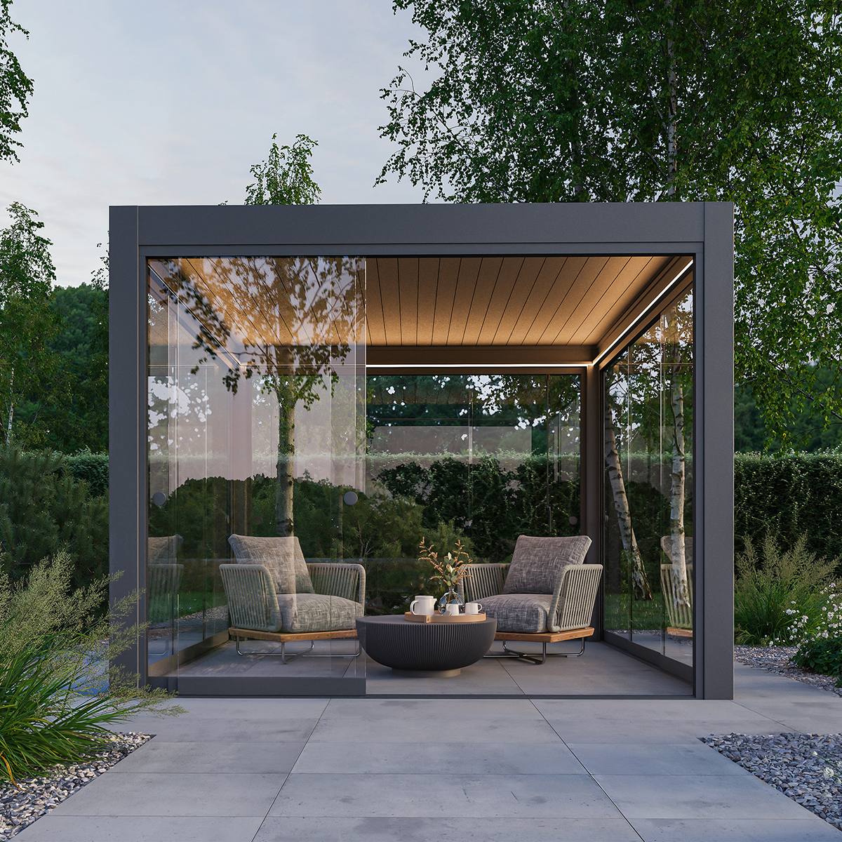
Plan pergola lighting
Lighting is part of both electrical and visual planning. It should make seating and circulation areas useful without dazzling people or causing distracting reflections in glass. Information about different use concepts is available in the ideas for pergolas on patios and in gardens.
Integrated lights must be intended for the specific pergola system or explicitly compatible with it. Drilling into profiles can affect water management, finishes and cable channels. Retrofitted surface-mounted lights also need suitable fixings and an outdoor electrical supply.
Questions before choosing a lighting layout
- Should lighting mainly illuminate a table, walkways or the full roof area?
- Is one shared switch needed, or should lighting be divided into zones?
- Where could reflections occur on windows or future glass walls?
- Where can power supplies or control components remain accessible?
- Should operation use wall switches, compatible remote control or existing building automation?
- Will lighting remain independently controllable when the louvre drive is switched off?
Anyone weighing up a fixed or movable roof should also consider the guidance on bioclimatic louvred roofs and glass roofs because roof type and lighting design influence one another.
Prepare for later equipment without oversizing
Useful provision may consist of an accessible conduit, a documented cable route or sufficient planned space in a suitable connection area. It is not sensible to permanently connect unknown future loads in advance. Future accessories may need different voltages, control protocols or connection locations.
Planned glass walls deserve particular attention. The guide to sliding and fixed pergola glazing shows the structural differences. Cable exits, switches and maintenance openings must not occupy future running tracks or fixing zones.
Recommended installation sequence
- Set the use and pergola type: define size, installation type, roof function, lighting and possible later side walls.
- Survey the site: record the building, levels, patio build-up, foundations, drainage and existing services.
- Check product documentation: confirm the motor side, connection data, control components and intended cable entries.
- Create a coordinated trade plan: the pergola installer, foundation contractor and electrical professional use the same dimensions and reference points.
- Prepare cable routes: install and mark routes and penetrations professionally, then photograph them before closing.
- Complete foundations and surfaces: protect cable ends and check their location again against the installation drawing.
- Install the pergola: route cables only through intended areas; do not make unplanned holes in profiles.
- Make electrical connections: the electrical professional carries out testing, connections and documentation for the particular system.
- Commission the functions: check motor operation, controls, lighting and isolation options.
For general product selection, consult the practical guide to aluminium pergolas and the overview of Bloomcabin pergolas .

Checklist for delivery day and installation preparation
- Delivered model, specification and documentation match the plan.
- Components are stored dry and safely without obstructing the work area.
- Post and motor sides are marked on the site plan.
- Foundations and fixing surfaces are ready and checked for installation.
- Cable exits sit within the intended connection area.
- Cable ends are protected, de-energised and clearly labelled.
- Connection and control components are fully identified.
- The electrical professional knows the planned testing and final connection date.
- Drilling, installation and maintenance areas remain freely accessible.
If anything is uncertain, contact Bloomcabin here before installation. Clarifying a discrepancy costs less than rerouting later.
Commissioning motor, controls and lighting
Before the motor is first operated, check that no tools, packaging or fixings are within the louvres’ movement area. Electrical testing comes before functional testing. Then move the roof gradually and observe smooth running, correct end positions and unusual noises.
Pair remote controls and wall controls according to their instructions. Then test each command individually. For lighting, check switching zones, dimming and shut-off behaviour only where these functions are actually provided. Sensors should be activated only when their location, assignment and response have been clearly confirmed.
If the drive jerks, sounds unusual or runs in an unexpected direction, do not keep operating it. Isolate the supply and have the installation, wiring and settings professionally checked.
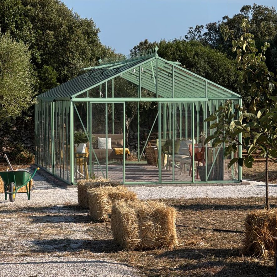
Maintenance and fault-finding
Electrical components need visual checks, especially after building work, severe weather or changes to the patio. Check for visible damage, loose covers, signs of moisture and crushed cables. Keep aluminium profiles and drainage paths clean; the page on caring for aluminium structures explains general maintenance principles.
If there is a fault, first establish whether it affects only the motor, only the lights or the whole system. Then check the control device, visible isolation states and obvious obstructions. Electrical enclosures must not be opened by unqualified people. Guidance on seasonal use and weather is available in the article using a pergola in winter.
Coordinate the pergola with other Bloomcabin structures
Where several garden structures stand on the same property, prepare one combined site and services plan. This applies, for example, to a pergola, greenhouse or conservatory, garden shed and outdoor sauna. Shared routes may make planning sense, but do not mean all loads may use the same circuit.
A sauna, such as the Elma S outdoor sauna, has a different use and electrical design brief from a louvre drive. Plan every structure using its own documentation. Information about the company and product range is available under About Bloomcabin and in the Useful information section.
Frequently asked questions
Can an electrician prepare the supply before the pergola is delivered?
Yes, if approved documentation is available for the exact model. The motor side, connection point and electrical data must be confirmed. Otherwise, take the cable only to an accessible handover point.
Can an existing outdoor socket be used?
Only after professional assessment. The socket, supply cable, protective measures, existing load and suitability for permanent use must be evaluated. Its proximity to the pergola alone is not enough.
Does every louvred pergola use the same motor voltage?
No. Motor, power-supply and control concepts differ. Only the documentation and markings for the delivered system are binding.
Should the motor and lighting be on one circuit?
That depends on connection loads, the control concept and the local installation. Separation can improve operation and fault-finding, but must be decided for the project by an electrical professional.
Can a cable be concealed in a pergola post?
Only if the specific system provides a suitable cable route. Drainage, fixings, sharp edges and maintenance access must not be compromised. Avoid unplanned drilling in profiles.
Can lighting be added later?
A retrofit may generally be possible. It is easier where an accessible cable route has been prepared. Lights and fixings must be compatible with the pergola, outdoor environment and electrical installation.
Where should a wall switch be installed?
At an accessible, suitable position from which roof movement can be observed where possible. Consider weather exposure, building use, children’s access and future glazing when choosing the location.
Can the pergola be operated when it is out of sight?
Unobserved movement may mean obstacles or people are missed. Follow the intended operating method and all manufacturer safety instructions. Remote operation does not automatically make every operating location suitable.
What changes if glass walls are added later?
Walkways, fixing zones, switch access and reflections can change. Cables and junction boxes must not obstruct the glazing track. The extension should therefore already be considered in the site plan.
Who may make the final electrical connection?
Permanent connection and required testing belong with an appropriately qualified electrical professional. The applicable requirements must be determined from local rules and the specific installation.
Which documents should be kept?
Keep installation and electrical instructions, model identification, wiring or cable plans, test records, photos of concealed routes, labels and documents for later alterations. Everything should be clearly assigned to the same installation.
What should happen if documentation and rough-in work do not match?
Stop installation or connection at that point. Clarify discrepancies with the supplier, installer and electrical professional. A cable must not be made to fit using improvised extensions or untested adaptors.
Final planning checklist
- Exact pergola model and orientation are confirmed.
- Motor, control and lighting data are available in writing.
- Foundation, drainage and cable routes are coordinated in one plan.
- The supply cable ends at the confirmed connection point.
- Mains, control and signal cables are correctly assigned.
- Maintenance access remains reachable after installation.
- Later glass walls or electrical additions have been considered.
- All cables and switching points are documented and labelled.
- Final connection, testing and commissioning are arranged with an electrical professional.
Good electrical planning remains invisible after installation. Its value appears in reliable operation, clear maintenance access and the ability to isolate faults. Further technical and design topics are available in the Bloomcabin blog and the useful information section.
