



MATERIALS
Making Sense of Greenhouse Plans and Measurements
Work systematically through greenhouse plans, elevations, dimensioned details and assembly documents. This guide helps you check the outer profile and supporting base, door area, levels, interior space and connections before ordering and construction.
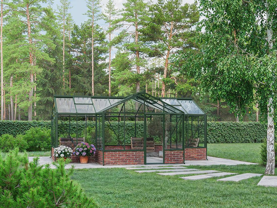
Technical greenhouse drawings compress essential construction information into a small space. They identify occupied areas, component junctions and necessary clearances for foundations, installation and use. Confusing nominal dimensions with the outer footprint, foundation size or unobstructed interior commonly causes errors, even where the geometry itself is straightforward.
Consider the complete set of plans, elevations, detail sheets and installation instructions together, rather than relying on one dimension. Resolve doubtful sizes in writing before making the base. This particularly matters for large orangeries, T layouts and structures attached to an existing wall.
Start by identifying each drawing
What you can establish depends on the drawing. A plan view looks down on the greenhouse, revealing its width, length, door position, overall form and foundation outline. A front, side or back elevation sets out vertical information such as eaves, ridges, roof slopes, heights and the pattern of wall and roof panels. A section view represents a cut through the building, exposing clear headroom or the way profiles join.
Exploded views and assembly stages explain how parts are ordered, orientated and fixed. Enlarged details focus on individual junctions, including the plinth, door sill or wall profile. A perspective image can clarify the three-dimensional form, but it is generally unsuitable for accurate site set-out.
Record the model name, version, revision and view on each sheet. For apparently symmetrical structures, identify north or label the garden side to prevent confusion between left and right.
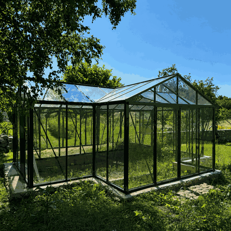
Recognising the principal measurements
Overall length and width
A stated length or width might run between outside profile edges, plinth edges, structural centrelines or foundation edges. Follow the arrowheads and extension lines to identify its endpoints. Lines reaching the furthest profile faces usually denote an outside dimension; lines stopping at a recessed base may instead describe the plinth or bearing footprint.
Multiplying the length and width of a rectangular model does not establish its full site requirement. Eaves, downpipes, a moving door and construction access can all sit beyond the drawn footprint. Compare available shapes under Greenhouses and Conservatories, and explore complex layouts in Orangery Sizes and Designs.
Eaves, ridge and maximum height
The eaves height is taken at the meeting point of roof and side wall, while ridge height reaches the peak of a conventional gable. A separate overall height can include additional parts. In every case, identify the drawing’s lower datum: finished foundation surface, ground, underside of the plinth or another nominated level.
Vertical dimensions affect more than standing room. They determine clearance from branches, gutters, projecting masonry and other site features. Because an open roof vent can extend outside the closed envelope, assess both operating and closed positions.
Measuring the doorway
At least three door measurements may appear: the rough or framed opening, the unobstructed passage and the complete door unit’s outside size. A wheelbarrow, potting bench or machine must fit through the clear passage; the outside frame dimension does not reveal the actual usable opening.
Allow for the chosen door’s operation: hinged panels sweep across an arc, while sliding ones travel along the façade. Consider threshold height and the eventual path construction too. Assess the door in relation to the foundation and both internal and external routes.
Bays and glazing divisions
Aluminium greenhouses often repeat a standard bay. A dimension string may represent structural centrelines, separate pane widths or total length. Combine component measurements only when their reference points match. End bays and profile widths can prevent an assumed sum of panel widths from equalling the true outside dimension.
Bay spacing can inform the positioning of shelves, vents, accessories and plants, but it is not an adjustable building module. For details on multiwall-sheet behaviour, read Using Polycarbonate in a Greenhouse. Specifications for the chosen model take precedence.
Interpreting dimension-line notation
Most technical dimensions combine a numeral with a dimension line, arrowheads or end markers, and extension lines that identify the measured points. One unbroken dimension gives the full span; a chain divides it into segments. Brackets or other notation may indicate reference-only information. Because conventions vary, use the legend supplied with that particular drawing rather than guessing.
Symbols have specific meanings for diameters, radii, angles, slopes and elevations. Drawing conventions also distinguish centrelines and concealed edges from actual external boundaries. If a legend is missing, clarify any symbol whose interpretation matters to construction.
Do not scale a screen image or print
Screen zoom, display dimensions and page fitting affect a PDF’s apparent size, making ruler measurements unreliable. Printing can enlarge, shrink or distort it as well. Written dimension figures take priority over the displayed scale unless the document explicitly specifies otherwise.
Where a sheet is marked “not to scale”, including by an abbreviation, rely solely on the stated measurements. Do not estimate an omitted value from the image.
Verify the units on every sheet
Check the stated units: product drawings often use millimetres, whereas site layouts frequently use metres; centimetres may appear too. Working across these documents risks unit errors. Include units in your own calculations throughout, converting at the end.
Watch decimal notation as well. Software and spreadsheets configured for different languages may interpret commas and full stops differently, so verify imported values.
Model size, footprint and clear interior
A size label can simply organise a product range and need not equal the outside footprint exactly. The model’s nominal size should not therefore be adopted as its foundation dimension. The true bearing footprint defines the outline needed by the plinth or base, while the clear usable interior loses space to frames, braces, doors and fittings.
| Measurement | Main purpose | Confirm before building |
|---|---|---|
| Nominal size | Sorting and comparing models | Never copy directly to the foundation |
| Largest outside dimension | Clearance and site planning | Include projections and moving parts |
| Plinth or bearing footprint | Designing the supporting base | Verify datum edges and square |
| Clear inside dimension | Benches, paths and activities | Include braces and doorway space |
Other outdoor products use comparable terminology. The Guide to Pergola Sizes, Planning a Pergola Foundation and the page for the Elma S Outdoor Sauna illustrate why catalogue size, physical outline and required installation area are separate concepts.
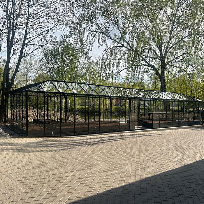
Divide an irregular plan into zones
Break complex plans into rectangles and connecting areas to check T configurations, orangeries and projecting sections. Mark the main body first, followed by cross-wings, entrance zones and recesses. Record each area’s width, length and position relative to the shared axis.
- Trace the furthest outside perimeter.
- Draw in principal axes and symmetry.
- Measure each zone independently.
- Mark and count every re-entrant and outside corner.
- Reconcile chained measurements with the total.
- Add doorway and access routes.
Dimensions can be mathematically consistent while the building is reversed or rotated on the block. Establish a named reference face, such as “house side” or “garden gate”, before proceeding. Ideas drawn from Victorian Greenhouse Design belong after this basic technical orientation is settled.
Set the drawing out on the site
Start from a dependable reference line rather than marking four corners independently. This could follow the house alignment, a string axis or a precisely surveyed baseline. Set further points at right angles from it, using different colours to distinguish the building outline from its foundation.
Check local conditions before starting. Consult the appropriate council and state or territory authority about requirements for the particular property and construction, including approvals or notifications. The article Greenhouse and Pergola Approval Checks offers an introduction; the current local requirements applicable to the project remain decisive.
Look beyond the corner points
Four corners do not adequately define a long or articulated footprint. Verify intermediate axes, recesses, junctions and the doorway. Check both diagonals as well as every side. Matching diagonals indicate square geometry only in the appropriate shape and say nothing about the surface level or flatness.
Record gradients, high spots and changes in level too. An accurate horizontal outline may still be impossible to assemble correctly on uneven ground.
Mock up the footprint where space is limited
Use string lines, marking paint or battens laid flat to show the full footprint. A ladder or box can help indicate eaves or ridge height. Try opening gates and moving a wheelbarrow along the proposed access. Testing at full size reveals clashes that a small drawing can hide.
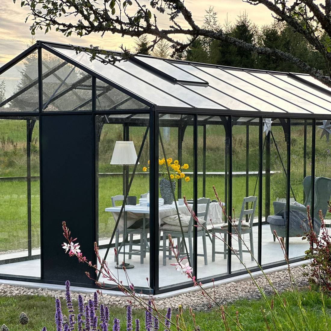
Plans for lean-to and wall-connected models
For lean-to construction, the existing wall matters structurally and geometrically. Besides overall width and depth, check the connection height, roof pitch and position of wall profiles. Allow clearance for windows, pipes, roof overhangs and drainage.
Inspect the complete fixing length. Projecting plinths, sloping faces and uneven render may keep a profile from seating flat. The particular wall construction and its capacity require project-specific assessment. A comparable distinction appears in Attached and Freestanding Pergolas, with further design differences under Classic and Bioclimatic Pergolas.
Design the interior from clear dimensions
Usability depends on unobstructed widths, not an outside measurement minus an assumed frame thickness. Work from documented internal sizes or seek confirmation where clearance is critical. Allocate the main aisle, secondary paths, work surfaces, containers and doorway individually.
Tall plants require ridge clearance only where they stand; headroom falls towards the side wall under a pitched roof. Keep shelves away from braces, rainwater channels and opening vents. For crop-focused layouts, consult Greenhouse Lettuce Growing and Managing Temperature and Humidity. Keep the structure accessible as specified for installation and subsequent maintenance.
Consult documents in a practical sequence
Review the locally displayed assembly-manual library early. Work through the material in this order:
- Confirm the ordered variant and inclusions.
- Use the overview drawing for heights and perimeter.
- Locate the correct foundation or base plan.
- Check door orientation, plinth and junctions in the manual.
- Match the latest revision to the supplied paperwork.
- Resolve unknown dimensions before creating permanent work.
When documents disagree, visual plausibility is not a sound basis for choosing a dimension. Record the model, document title, revision and disputed measurement, then contact Contact Bloomcabin. Broader assistance is listed under Helpful Resources.
Delivery-day and pre-assembly checks
Before construction, compare the ordered model with the package count on the delivery paperwork and any visible part labels. Follow the provided directions when opening or storing packages. The site may have been set out correctly even though the selected or supplied variant has a different door arrangement.
- Does the delivered model and variant match the order?
- Is the door where the approved layout shows it?
- Has the finished foundation been checked for size and level?
- Is every necessary access zone clear?
- Have junctions and drainage paths been resolved?
- Do you have the applicable assembly instructions?
Ordering guidance is available under Buying and Delivery and Placing an Order. For Australian deliveries, with coverage extending to the country’s islands and territories, see Greenhouse Delivery Across Australia .
Frequent plan-reading errors
- Treating the model label as the foundation size: A rounded catalogue size is not a construction measurement.
- Consulting just one view: Plans and side elevations communicate different information.
- Mixing up inside and outside sizes: Paths and work zones may then become unusably narrow.
- Overlooking door travel: The opened door may strike a garden bed, step or fence.
- Reversing the layout: A perspective image is wrongly taken as the confirmed door handing.
- Scaling the PDF image: Screen zoom and printer settings distort the result.
- Confusing measurement units: Millimetre values are mistaken for centimetres or metres.
- Relying on diagonals alone: Intermediate positions, side lengths and levels go unchecked.
- Omitting service clearance: Drainage and exterior surfaces can become impossible to reach.
For long-term access guidance, read Maintaining an Aluminium Greenhouse. Practical observations under Greenhouse Customer Reviews may be useful, but they cannot override the drawing for your model.
Checklist before accepting the layout
- Have the precise model and equipment package been confirmed?
- Which line is the largest outside dimension, and which defines the plinth?
- What datum is used for the ridge and eaves?
- Where is the unobstructed doorway, and what path does the door follow?
- Does the site plan show the structure in its intended orientation?
- Is there access outside for building, cleaning and drainage?
- Are trees, services, wall projections and ground falls recorded?
- Can the component, total and diagonal dimensions be reconciled?
- Has the foundation design been confirmed for this site and model?
- Have project-specific authority checks been completed before work?
Common questions
Do greenhouse listings show inside or outside dimensions?
Do not infer the basis where it is not labelled. A product overview often uses a nominal or outside size, while detailed drawings may add internal and plinth dimensions. Follow the arrowheads, datum lines and legend on the applicable document.
Can the product-page measurements be used for my foundation?
Cross-check against the specific foundation, base or assembly drawing first. Product webpages mainly assist selection. Confirm critical dimensions before undertaking concrete, masonry or any other construction that cannot readily be altered.
Why can the nominal and drawn sizes differ?
A nominal description may be rounded to organise models within a range. Technical drawings instead dimension specified reference points. The real size can differ because of profiles, plinths and the way structural bays are divided.
What is meant by “not to scale”?
Do not derive dimensions by measuring the drawing with a physical ruler or screen tool. Use the labelled figures. Ask for any required dimension that the document does not provide.
How do I establish the door side?
Locate the doorway marking, opening direction or part identification in the floor plan. Establish your viewing side at the same time. Obtain confirmation wherever a mirrored version is possible or the drawing leaves orientation uncertain.
What should be measured for a lean-to model?
Record depth and width as well as fixing height, eaves level, roof peak, roof angle, profile locations and clearance to existing features. Also assess whether the wall face is flat and whether its construction is structurally suitable.
What clearance is needed around the greenhouse?
No universal distance suits every product or block. Allow for the assembly method, cleaning, window travel, drainage and access paths, then ask the relevant authorities about site-specific requirements. The resulting service area must remain genuinely usable.
Do matching diagonals confirm a correct foundation?
Not by themselves. They are valuable when checking rectangular geometry, but side lengths, intermediate positions, surface flatness and level still require verification. Test every section of an irregular footprint separately.
Which measurement governs when documents disagree?
No particular document category automatically takes priority. Confirm the model and revision of each document, then obtain the applicable measurement from the supplier. Leave the foundation unchanged until the discrepancy is resolved.
Where are care and warranty details provided?
Commercial terms appear under Warranty Information. Consult care instructions separately: dimensioned drawings describe geometry, assembly documentation guides construction and maintenance information addresses upkeep.
Completing the drawing review
Make the last review at the marked-out location as well as at your desk. Recheck the model, document revision, outside perimeter, plinth, heights, doorway, diagonals and junctions. Then consider operation: can the door move completely, do the paths stay open, and can you reach roof vents, gutters and outside faces?
Planning is dependable only when the product documents, foundation plan, assembly instructions and site marks all use identical reference points.
Enter the accepted measurements on a short checklist and photograph the site marks, creating a record of the planned variant. More ideas for using the structure are available from the Bloomcabin Blog; however, technical choices must follow documentation for the selected model.
