



PREPARATION
Pre-order site survey: greenhouse, pergola and outdoor sauna
A useful survey records far more than width and length. Work through the property, foundation, levels, wall junctions, doors, utility routes, drainage and assembly access.
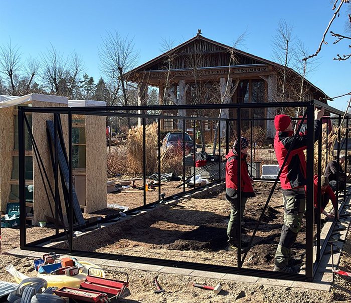
A sound order starts with exact site data. Two rough side measurements do not adequately describe a greenhouse, pergola or outdoor sauna location. Record heights, diagonals, falls, foundations, roof projections, circulation clearances, service runs and the route into the assembly area.
Homeowners, designers and assembly contractors can use this guide to document a location systematically. It cannot replace the chosen model's drawings or a check of local requirements. The relevant product documents and rules applying at the installation address remain decisive.
Survey first, then settle on a model
Begin with the space that can actually be used rather than a nominal product size that might barely fit. Those site findings determine the practical form, orientation and dimensions.
Map boundaries, buildings, walls, paths, trees, beds, pits and services. Investigate planning or building approvals where applicable. Read Greenhouse and pergola approval pathways for an overview; confirm your project's requirements with the relevant authority and council.
The footprint is only part of the space requirement. Make provision for door travel, eaves, water disposal, upkeep and construction work. Even when the shell fits, blocked door movement or an inaccessible side can make the arrangement unworkable.
Four measurement rules that always apply
- Measure twice: Take each critical dimension on at least two occasions. Whenever practicable, a second person should verify longer spans.
- Question every apparent right angle: Existing patios, foundations and walls commonly vary from a true rectangle, so take both diagonal readings.
- Record heights separately: Plan views conceal slope. Record the level variation at each corner and wherever the ground changes noticeably between them.
- Keep site readings distinct from design figures: Keep actual readings, intended set-out positions and manufacturer dimensions in separate columns. This prevents an assumption from being recorded as a site condition.
Avoid rounding a reading merely because the result is easier to use. Approximate figures may assist early selection, but confirm every required product and interface dimension before ordering or constructing the foundation.
Gather the right tools and records
- a robust tape measure and fit-for-purpose distance measurer;
- a spirit level, long straightedge or appropriate levelling instrument;
- pegs and string, plus chalk or removable marking tape;
- a square, plumb bob and a ladder only where height readings can be taken safely;
- paper, a plan-view sketch and a camera for documentation;
- the proposed model's drawing, foundation plan and assembly manual;
- records covering existing footings, underground services and drainage.
Related ranges and planning material are available under Useful information, in Greenhouses and conservatories and in the Sauna section. Before building a base, clarify through Contact to confirm which documents apply to the selected product.
Map the whole site
Sketch the proposed location from above. Exact scale is unnecessary, but the orientation must be unmistakable. Show north, every boundary and a permanent reference feature such as the corner of a building.
Tie the proposed structure to at least two lasting reference lines with measured offsets. Show its sides, corner-to-corner readings, door arcs and maintenance routes. Add a dimensioned elevation wherever it meets a building.
| Plan item | Record |
|---|---|
| Site and existing features | Boundaries, buildings, walls, paths, vegetation, pits |
| Planned structure | Outer outline, orientation, doors, roof edges |
| Heights | Corner levels, falls, steps, thresholds and wall connections |
| Services | Service routes, outlets, drainage direction |
| Logistics | Vehicle access, carrying route, pinch points and assembly area |
Dimensions needed for every structure
For any of these products, your notes should include:
- the full usable width and length;
- two corner-to-corner measurements across the marked outline;
- a height reading for each corner;
- clearances from boundaries, walls and obstructions;
- the tightest clear passage along the carrying route;
- headroom beneath branches, roof edges and overhead services;
- nearby door and gate widths, including their direction of travel;
- the exact locations of pits, cables and pipes;
- working room for assembly, ladder use and later servicing.
Add intermediate readings wherever the area is irregular. Walls that appear straight can bow, patios may taper into a trapezoid, and a kerb can conflict with the intended location of a post.
Set the structure type before finalising its outline
Pergola form determines site and foundation needs: attached models need a suitable wall; freestanding models need defined perimeter supports. The comparison Comparing attached and freestanding pergolas helps you choose.
How the roof operates influences runoff, usable headroom and adjacent façades. Read Bioclimatic or classic pergola and, for further background, Understanding a bioclimatic pergola.
A rectangular cabin and a barrel sauna occupy and use their surroundings differently, particularly around access. Compare Elma S, Elma L and the HC150 barrel sauna from their individual technical documents rather than relying only on photographs of gardens.
Greenhouse measurement checklist
- Plot the sun's course, areas of shade and the direction of the structure's long axis.
- Verify the entire footprint, including any plinth or foundation zone.
- Include the selected door side, its full travel and step-free entry.
- Inspect the eaves and ridge zones for branches, services and nearby roof overhangs.
- Reserve operating and cleaning room around vents, windows and their openers.
- Allow for water supply, rainwater discharge and moving growing media into the structure.
- For attached designs, map window sills, downpipes, plinths and every façade projection.
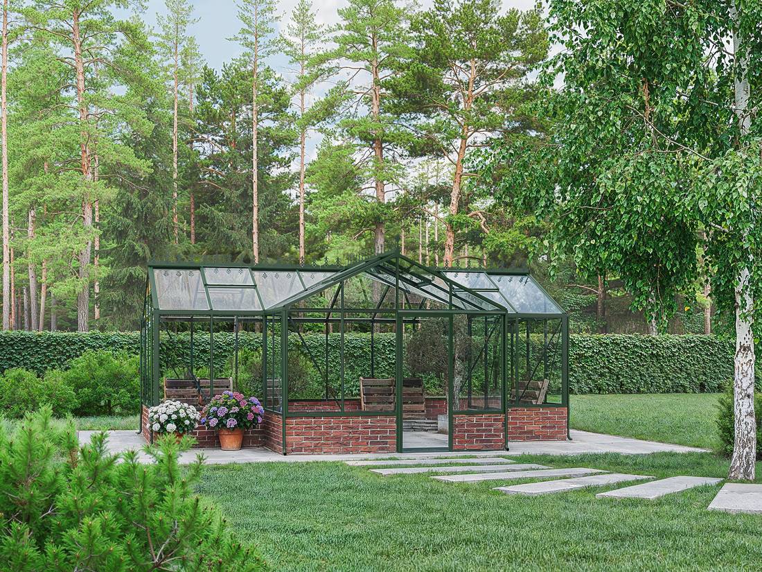
Designs inspired by historic glasshouses, or divided into complex geometric bays, may introduce further axes and junctions. The article about Victorian greenhouses explores their design language; measurement must still follow the drawings issued for the exact model.
Pergola measurement checklist
- Take patio width and depth readings in several locations.
- Confirm a sound load-bearing location for every planned post.
- Account for overhanging roof elements and any built-in drainage path.
- Compare available headroom with doors, windows and roller shutters.
- Plot the operating envelope of louvres, blinds and glazing.
- Note how the patio currently sheds rain and where splashback occurs.
- Identify exposed sides and record the surroundings for a site-based design assessment.
For help selecting dimensions, use the Pergola size guide . The article Aluminium or timber covers material choice and intended use. Where side walls are planned, include panel travel, stops and floor levels in the measurements; also see Pergola with glass walls.
Outdoor sauna measurement checklist
- Map the full placement zone, with room for entry and maintenance.
- Show the door, its opening direction and a safe landing area outside.
- Match isolated foundation points or continuous supports to the relevant product documentation.
- Trace utility runs needed by the equipment selected for the sauna.
- Resolve site-specific arrangements for cleaning and water disposal.
- Verify separation from plants, nearby buildings and other installations.
- Assess access width, height, bends and load capacity.
Do not assume several models share a standard plan. Consult the separate documents for HC 180, HC 225, HCF 225, HCF 300 and LC 225 individually. For general guidance, see Choosing a timber or barrel sauna.
Survey the foundation and patio
Do not assume an existing paved area can serve as the foundation. Note construction layers, edge clearances, joints, slope, visible defects and whatever is known about the support below. A competent project-specific assessment must cover load capacity, frost performance, anchorage and drainage.
For pergola-specific preparation, the Pergola base guide sets out the main questions. Mark drilling and bearing locations only from the approved drawing; dimensions inferred from product images are not reliable.
Verify a pegged rectangular outline
- Run string along each proposed outside edge.
- Take separate readings for both long edges and both cross edges.
- Record the two corner-to-corner lengths.
- When those readings disagree, reposition the corners and repeat the check.
- Establish the level at all four corners.
- Then tie every position back to one permanent reference.
Matching diagonal readings are useful evidence, but every side still needs verification. With an articulated footprint, test each rectangular component on its own.
Further checks for structures fixed to walls
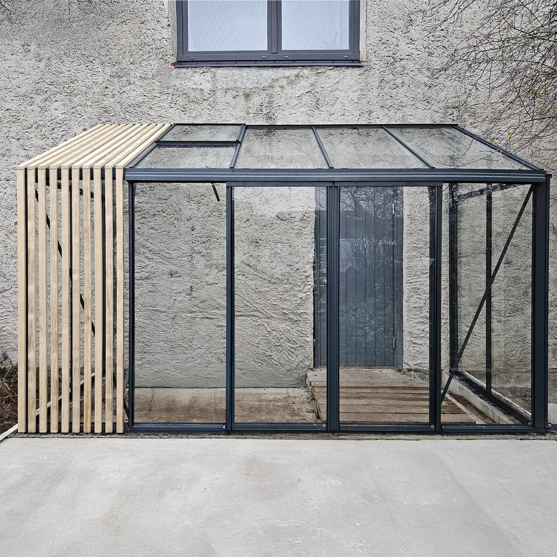
Draw a wall elevation and add dimensions. Include façade width, available fixing height, openings, roller-shutter housings, lights, downpipes, vents, outdoor taps, projections and changes in plinth depth. Inspect the future fixing-profile level as carefully as the base of the wall.
Wall construction and fixing capacity need an assessment specific to the property. Do not guess what lies behind insulation or cladding, or where the construction is uncertain. Bring in an appropriately qualified contractor early if necessary.
Plan doors, paths and internal space
Draw every door in the fully open position, then look for conflicts with paths, furniture, raised garden beds or doors in the existing building. Posts, benches and equipment should not constrict the main circulation route.
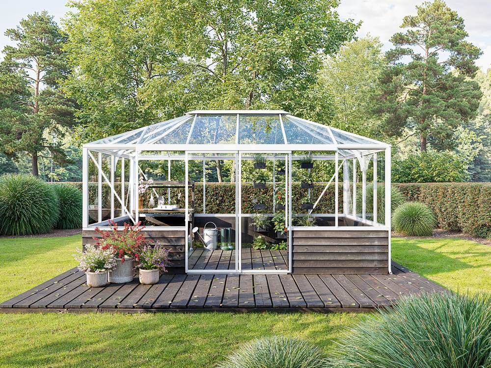
Lay out the interior before confirming orientation. Greenhouses need space for benches and wheelbarrows; pergola circulation depends on tables, chairs, a barbecue or an outdoor kitchen. For a sauna, consider entry, changing and safe passage back to the building. More layout inspiration appears in Patio and garden ideas for pergolas.

Utilities, drainage and site exposure
Show present and proposed utilities on the plan, including electricity, water, drainage and other installations. Design each connection only after reviewing the selected product's instructions and the technical rules applying locally. Where electrical work requires a licensed trade, use a suitably licensed local electrician.
When practical, inspect the location during rain. Map runoff, ponding and water discharged from buildings. Record shade, falling leaves, exposed wind directions and conditions through the local seasons, including winter where relevant. Seasonal-use advice is available in Pergola in winter. Assess local design loads and other site requirements separately.
Survey the delivery and working route
Measure the whole unloading-to-build route: minimum width and headroom, corners, steps, slopes, soft ground, gates and low branches. Check long components can turn and that the destination allows sorting and assembly.
Add any limits affecting shared areas and narrow driveways. One generous gate opening does not prove that every component can travel along the remaining path.
Anna Koku Skola: a practical survey sequence
Read the Anna Koku Skola photographs as stages within one installation. They indicate a sensible sequence: map the broad site, peg the intended outline, inspect foundation and connection zones, and preserve enough clear working room for assembly.
- Map existing conditions: Sketch permanent reference features together with each obstruction.
- Peg the proposed form: Use string to display the intended outline on the ground.
- Verify the shape: Take independent readings for sides, diagonals and levels.
- Review interface points: Check wall, ground and drainage zones against the documentation.
- Test everyday use: Swing doors, walk the circulation paths and mark internal zones.
- Complete the logistics review: Recheck the carrying path and working area at the end.
Do not treat the photographs as unrelated builds. Each captures another stage or viewing angle within the same installation.
Measurement worksheet before ordering
| Check item | Actual value or result | Status |
|---|---|---|
| Available length and width | Enter | Open/checked |
| Diagonal A and B | Enter | Open/checked |
| Heights at all corners | Enter | Open/checked |
| Distances to boundaries and existing features | Enter | Open/checked |
| Door and walking routes | Describe | Open/checked |
| Base condition | Describe | Open/checked |
| Services and drainage | Mark | Open/checked |
| Transport route | Enter narrowest point | Open/checked |
| Product drawing checked | Note document version | Open/checked |
Final review before releasing the order
- Model identity and selected configuration are unambiguous.
- Every dimension was taken at the real installation address.
- The structural outline, projections and operating envelopes are recorded separately.
- Levels and corner-to-corner readings have been verified.
- The foundation and anchoring assessment considered more than the visible finish.
- Every wall junction and façade obstruction is on the plan.
- Space allowances include accessories and anticipated additions.
- The carrying path and assembly area are workable.
- Applicable state or territory and council requirements have been checked with the relevant bodies.
- No unresolved technical query remains when the order is released.
Company details are provided on About us . Other garden-product categories that may affect a coordinated layout appear under Garden houses.
Reconcile the documents again after purchase
When the order-specific package arrives, compare it with the site records again. Verify the model name, orientation, outside dimensions, support positions, door locations and interfaces. Never begin foundation or utility work from an outdated sketch, a related model or an unverified screen image.
Issue the same current document revision to the foundation contractor and assembly crew. Add every site change to that documentation and repeat the relevant checks.
Allow for servicing as well as construction
A structure that can be assembled may still be awkward to service. Preserve access for cleaning, caring for hardware, inspecting drainage and replacing reachable parts. Keep vigorous shrubs and trees away from components that need routine examination.
Check ladder positions, access for glass cleaning and the ability to reach roof margins. Required working room varies with the model, setting and maintenance task, so a single generic clearance must not be treated as mandatory.
Frequently asked questions
Can the footprint on the product page be used for ordering?
Not by itself. Establish the basis of that figure, then identify any separate allowance for roof projections, fixing zones or circulation. Use the documentation issued for the precise model selected.
How do I verify a rectangular outline?
Compare its two diagonal readings; a correctly formed rectangle gives matching results. Also verify equal opposing sides and check that each corner is at its intended level.
Might an existing concrete patio be suitable?
It may be, but appearance alone cannot establish suitability. The construction, condition, slope, edge distances, load capacity, frost behaviour and anchoring options all need to suit the project. Professional assessment may be necessary.
What surrounding clearance is required?
No single figure applies. Determine the clearance from door operation, overhangs, cleaning access, construction needs, drainage, property constraints and local requirements for the selected model.
Which details matter for attached greenhouses and wall pergolas?
Prepare a dimensioned wall elevation in addition to the plan. Show available connection height, façade width, plinths, openings, service routes, downpipes, projections and the wall's construction.
Are site measurements still necessary when Bloomcabin supplies drawings?
Yes. Product drawings define the structure, whereas your survey records the property. Comparing the two establishes whether the proposed assembly, operation and installation are feasible.
At what stage should an installer be consulted?
Before foundations and services, seek advice on slopes, restricted access, wall mounting or uncertain existing construction. Resolve assumptions before irreversible work.
How should a sloping garden be surveyed?
Take levels at every corner and at meaningful points between them; an average slope is insufficient. Choose the foundation and any ground adjustment only after considering both the location and the product.
Should future accessories appear in the survey?
Yes. Glazed or solid sides, shade systems, gutters, equipment, steps, furniture and later additions may alter space needs, connections or foundation zones.
Which surveying mistake occurs most often?
Recording only nominal width and length is a common shortcut. It ignores diagonals, changing levels, moving doors, projections and the assembly route. A properly documented site plan captures those constraints.
