



Power planning for motorised pergolas: louvre drive, control gear and lights
Electrical design for a motorised pergola belongs in the broader site plan. The guidance below identifies what must be known before cabling, how power and control runs should be coordinated, and what to allow for during lighting design, commissioning and later upgrades.

Structure, footings, drainage and electrical equipment form one planning task for a motorised pergola. Leaving cable decisions until assembly can produce exposed wiring, extra holes or connections that are difficult to reach. Coordination among the owner, pergola installer and electrician should therefore begin early.
Use this guide for project planning, not as a substitute for the technical documents issued for the chosen model or for assessment and work by a qualified electrician. Confirm ratings, protection arrangements and location-specific requirements for the individual installation.
What needs an electrical supply on a motorised pergola?
The roof-louvre actuator is the clearest electrical load. A particular system may also supply a control box, receiver, transformer, wall control, built-in lighting or optional sensors. Wireless handsets are usually separate from fixed wiring, although the pergola still needs their compatible receiver.
A given bioclimatic pergola may use a different electrical arrangement. Its motor might take mains power directly, connect through a separate transformer or rely on proprietary control equipment. Appearance alone reveals neither the correct voltage nor the required cable and connection method.
- Roof-louvre actuator: drives the louvres and requires a clearly allocated electrical supply.
- Control equipment: interprets commands from switches, handsets and compatible sensors.
- Lights: may be built in, surface-fitted or installed independently.
- Possible additions: include sensors or future side elements containing electrical parts.
Details to settle before the electrical rough-in
Settle the precise model before cutting chases, drilling or laying buried cable. First use the comparisons for a bioclimatic versus classic pergola, wall-fixed versus freestanding layouts and pergola dimensions to establish the main construction parameters.
| Detail to establish | Planning significance |
|---|---|
| Confirmed model and configuration | Identifies its actuator, controller, lighting options and designated connection locations. |
| Orientation and post layout | Indicates safe cable outlets that will not interfere with drainage or footings. |
| Actuator and controller side | Avoids bringing the incoming supply to the opposite end. |
| Manufacturer’s electrical information | Provides the authoritative connection requirements and compatibility details. |
| Chosen operating points | Shapes the routes for controls, switches and any secondary operating position. |
| Lighting and upgrade plans | Supports prudent future provision without fitting equipment that has no use. |
The chosen pergola family must be matched to its current assembly manual as well. General sketches and marketing images do not provide enough information for an electrical rough-in.

Design the pergola and electrical installation from one site plan
Base the wiring layout on the dimensioned drawing used for footings and assembly. Plot the building supply point, pergola grid, posts, footing bodies, terrace layers, drainage direction, cable corridors and outlets on that single plan. The guide to pergola footings explains why the supporting base needs resolution ahead of assembly.
Keep wires clear of fixing areas and do not let them surface where the roof discharges water. Position conduit ends so posts cannot crush them and fasteners cannot strike them. With an existing terrace, include its total build-up, waterproofing and any movement joints in the design.
Before construction, identify any planning or building checks relevant to the address. Use the localised guide to Australian pergola approvals as an initial reference, then ask the relevant state or territory and council what applies to the site and proposal.
Routing power to freestanding and wall-fixed pergolas
Freestanding layout
On a freestanding layout, power commonly travels below ground to a nominated post. The electrical contractor must select the route, burial arrangement, mechanical safeguards, cable and entry detail for the actual conditions. A conduit helps only when its diameter, bends, seals and termination match the cable to be installed.
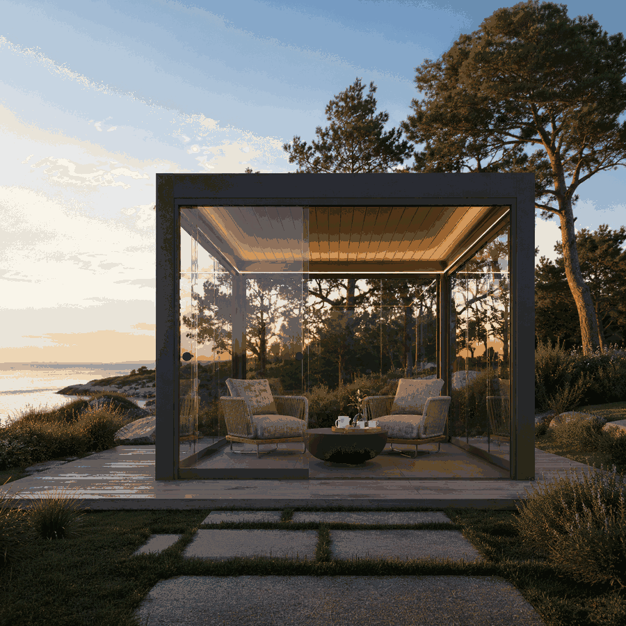
Align the outlet exactly with the assembly drawing. A loosely estimated point inside the footing can end up below a base plate or beyond the post profile. The product page for the Bloomcabin freestanding pergola shows the relevant form.
Wall-fixed layout
With a wall-mounted pergola power may be brought through the building, but the shortest path is not necessarily suitable. Account for insulation, façade layers, waterproofing, structural members and wall-fixing locations. Any penetration through the wall needs an appropriate moisture seal.
Establish the actuator and controller side before choosing the cable route. The selected wall-mounted pergola version governs that decision; a perspective product picture cannot establish the outlet position.
Design the incoming supply and circuit
The electrician considers connected demand, cable distance, installation method, environmental exposure, protective arrangements and the existing switchboard. Those findings determine conductor size, overcurrent and residual-current protection, and whether a dedicated circuit is appropriate or necessary. One standard value cannot cover differing models, accessories and buildings.
Product instructions and the electrical design may permit the actuator and lights to share a supply or use separate ones. Individual circuits or separately switched outputs can make diagnosis easier, allowing the roof to remain available when only the lighting has failed. Extra complexity, however, needs a practical reason.
Do not assume that a nearby outdoor power point is suitable. An electrician needs to assess its condition, protection, circuit assignment and existing demand. Extension leads intended as temporary equipment do not provide a properly designed permanent outdoor supply.
Separate mains, control and signal cabling correctly
Wiring for unlike voltages or signal functions cannot simply be bundled or interconnected. The system and applicable requirements determine cable selection, enclosures and any separation distances. Particular care is needed where proprietary actuator leads interface with the building’s fixed installation.
Apply durable, unambiguous labels at each end of every run. Also photograph routes before they are covered and record them against fixed reference points. Where several conduits finish at different posts, identify each one. A draw cord assists future work but does not establish that a conduit remains suitable.
Placing the louvre actuator and controller
Keep the actuator, junction box and controller serviceable, yet neither exposed to weather nor needlessly on show. Service access does not require tool-free exposure; it requires a qualified person to reach equipment without avoidable removal of structural pieces, roof louvres or permanent trim.
Fit the controller only in the orientation and surroundings approved by its manufacturer. Allow for drainage paths, condensation, direct exposure and trapped heat. For a motorised Bloomcabin pergola always follow the model documentation rather than relying on customary installation practice.
Designing the pergola lighting
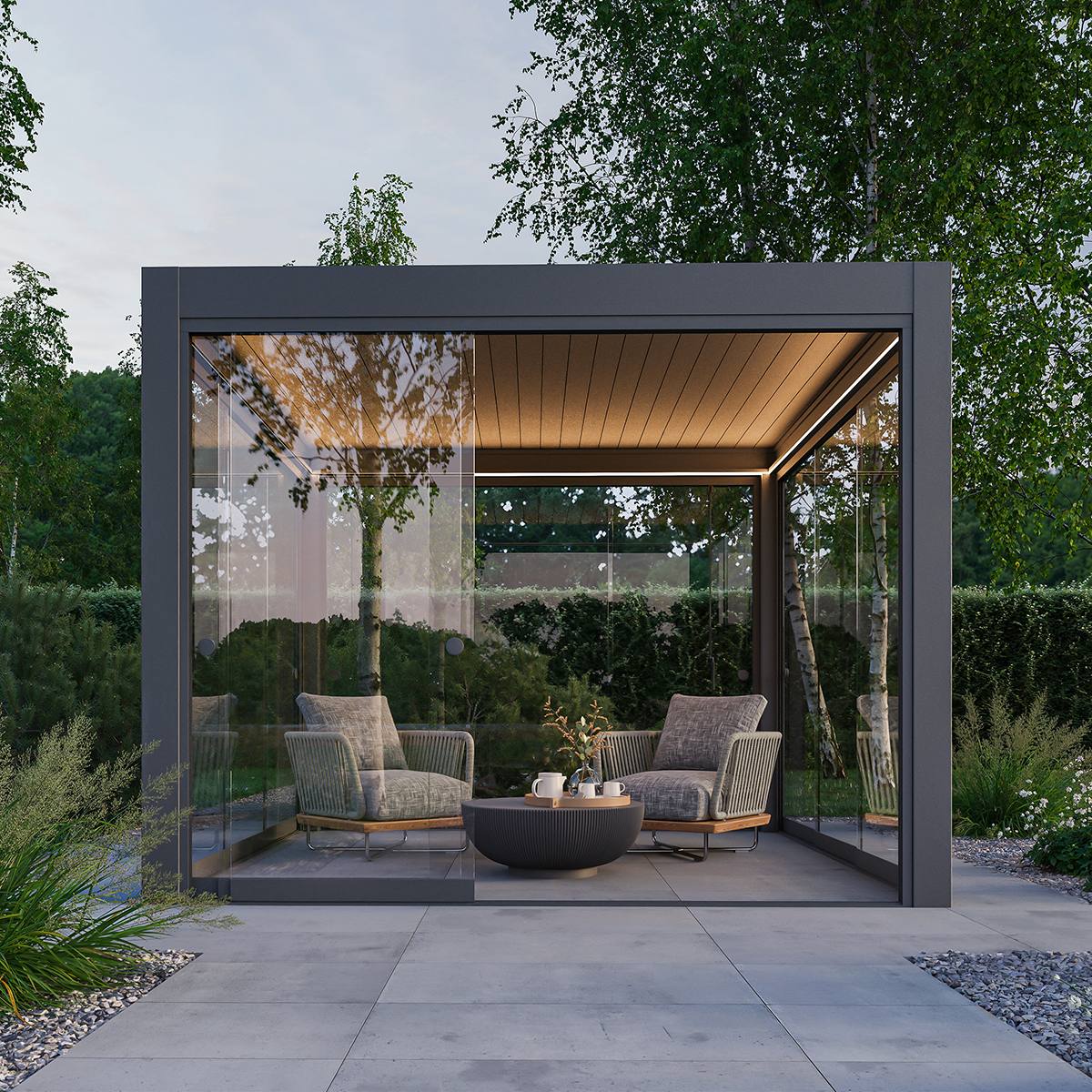
Treat lighting as both an electrical and spatial decision. It should serve tables and circulation areas without glare or troublesome reflections from windows and glazing. Explore the terrace and garden pergola ideas.
Built-in fittings must be made for the selected pergola or explicitly approved as compatible. Drilling a profile can disrupt drainage, finishes or internal cable channels. Surface-mounted additions still require secure attachment and an electrical supply designed for outdoor exposure.
Questions to answer before laying out the lights
- Is the priority a table, circulation route or illumination across the roof?
- Should one control operate everything, or are separate light zones wanted?
- Which windows or future glass panels could produce reflections?
- What accessible location can accommodate transformers and control gear?
- Will users operate the lights from wall controls, a compatible handset or building automation?
- Will the lights still work when power to the louvre actuator is isolated?
People comparing fixed and opening roof designs should also read about glass roofs and bioclimatic louvred roofs . The roof arrangement changes how the lighting performs.
Prepare for upgrades without excessive provision
Practical future provision could be a reachable conduit, a recorded cable corridor or spare room in a suitable connection zone. Avoid permanently wiring an unidentified future load. A later accessory may use another voltage, protocol or physical connection point.
Future glass sides require early thought. The comparison of fixed and sliding pergola glazing sets out their construction differences. Keep outlets, switches and access panels away from prospective tracks and fixing areas.
A practical order for the work
- Set the use and pergola form: choose its size, mounting arrangement, roof operation, lighting and possible future sides.
- Record site conditions: survey the building, levels, terrace layers, services, footings and drainage.
- Verify the product information: locate the actuator side, ratings, controller and designated cable entries.
- Coordinate all trades: give the installer, footing contractor and electrician one drawing and common reference points.
- Form the cable pathways: make and label routes and penetrations correctly, photographing them before concealment.
- Finish footings and surfaces: protect cable ends, then recheck their locations against the assembly plan.
- Assemble the pergola: use only its intended cable passages and avoid ad hoc holes in profiles.
- Complete the electrical work: have the electrician test, connect and document the particular installation.
- Bring each function online: verify actuator travel, controls, lighting and available isolation methods.
For help selecting the underlying product, see the aluminium pergola planning guide and browse the Bloomcabin pergola range .
Delivery-day and pre-assembly checks
- The delivered version and its documents correspond with the project plan.
- Parts are secure, dry and stored clear of the working zone.
- The site drawing identifies every post and the actuator side.
- Footings and attachment surfaces have been inspected and are ready.
- Each cable outlet falls inside its nominated connection zone.
- Cable ends are isolated, protected and labelled without ambiguity.
- Every connection and control component has been positively identified.
- The electrician has the intended testing and final-connection schedule.
- Work, drilling and future service zones remain unobstructed.
When details do not agree, reach Bloomcabin through the contact page before assembly begins. Resolving the mismatch first is preferable to rerouting a cable afterwards.
Commissioning the actuator, controls and lights
Before energising movement, remove tools, packaging and fasteners from the louvres’ operating zone. Finish the electrical tests before trying the functions. Then operate the roof in small steps, watching for smooth movement, correct stopping positions and any abnormal sound.
Program handsets and wall controls in accordance with their respective instructions, then try each command separately. Test lighting zones, dimming and switch-off behaviour only if the installed system provides them. Do not enable a sensor until its location, assignment and intended response have all been verified.
If the drive jerks, sounds unusual or runs in an unexpected direction, do not continue operating it repeatedly. Isolate the supply and have installation, wiring and settings professionally checked.
Inspection and troubleshooting
Visually inspect electrical parts after construction work, harsh weather or changes to the terrace. Look for damaged surfaces, displaced covers, moisture marks and trapped or crushed wiring. Keep drainage channels and aluminium profiles free of debris; broader maintenance advice appears under aluminium structure care.
Begin fault diagnosis by identifying whether the actuator, lighting or whole installation is affected. The user can then check controls, visible isolation states and obvious physical obstructions. Anyone without the required qualifications should leave electrical enclosures closed. For seasonal and weather considerations, read winter use of a pergola.
Plan alongside other Bloomcabin garden structures
If one property contains several garden buildings, map their positions and services together. The principle can cover a pergola, conservatory or greenhouse, shed and outdoor sauna. A shared corridor may be useful, but that does not establish that every load can be placed on one circuit.
For example, the Elma S outdoor sauna serves a different purpose and presents different electrical tasks from a louvre actuator. Design each structure from its own documents. An introduction to the business and its wider range is available under Bloomcabin company information and in Useful information .
Questions commonly asked
Can the supply be prepared before delivery of the pergola?
Yes, provided approved information for that exact model is available. Verify the actuator side, electrical data and connection position. If those details remain uncertain, stop the cable at an accessible handover location instead.
Is a nearby outdoor power point suitable?
Only if an electrician has assessed it. The check needs to cover the outlet, its supply cable and protection, current circuit demand and suitability for permanent operation. Proximity by itself proves nothing.
Do all louvred pergolas have matching motor voltages?
No. Designs for actuators, transformers and controllers vary. Treat the documentation and labels belonging to the delivered equipment as authoritative.
Can the actuator and lights use the same circuit?
Possibly, depending on ratings, control design and the site installation. Separating them can aid operation and diagnosis, but the electrician should make that decision for the individual project.
May wiring run inside a pergola post?
Only where the particular product provides an appropriate route. The cable must not conflict with drainage, fasteners, sharp edges or service access. Do not create unscheduled holes in the profile.
Is it possible to retrofit lighting?
A retrofit may be feasible and is easier where a reachable cable pathway was allowed for. Confirm that the fittings, attachments and electrical arrangement suit both the pergola and outdoor conditions.
What is a suitable position for a wall control?
Place it somewhere accessible and appropriate, preferably with a view of the moving roof. When choosing the point, consider exposure to weather, how the building is used, children’s access and any planned glazing.
Should the roof move while it is out of view?
Unobserved roof movement can conceal people or obstructions. Follow the manufacturer's operating and safety instructions; wireless control does not make every operating position suitable.
How do future glass sides affect the plan?
They may alter movement corridors, attachment areas, access to controls and reflected light. Neither cables nor connection boxes may obstruct the glazing system. Show this proposed upgrade on the original site drawing.
Who should make the permanent electrical connection?
Entrust permanent connections and required tests to a suitably qualified electrician. Check local and installation-specific rules. NSW wiring requires a licensed electrician's work or supervision.
What records need to be kept?
Keep assembly and electrical manuals, model details, wiring plans, test records, concealed-route photos, labels and alteration documents clearly assigned to this installation.
What if the rough-in conflicts with the documents?
Pause assembly or electrical connection when the conflict is found. Ask the supplier, installer and electrician to resolve it before continuing. Improvised extensions and adaptors that have not been verified must not be used to force the cable arrangement to fit.
Planning sign-off checklist
- The model, configuration and site orientation have been confirmed.
- Written specifications cover the actuator, controls and installed lighting.
- One drawing coordinates footings, drainage and every cable corridor.
- The incoming supply reaches the verified connection location.
- Mains, signal and control runs have the correct assignments.
- Service points can still be reached once assembly is complete.
- The plan allows for proposed glazing and electrical upgrades.
- Labels and records identify every cable and operating point.
- An electrician is scheduled for connection, testing and commissioning.
Well-planned electrical work is barely noticed after assembly. Its benefits are dependable control, practical service access and orderly fault diagnosis. Further design and technical guidance can be found in the Bloomcabin blog and the Useful information section.
