



MATERIALS
Greenhouse Drawing Guide: Dimensions, Bases and Clearances
Before a greenhouse is ordered or its base is prepared, use the drawings to verify what will actually occupy the site. This guide shows how to compare plans, elevations and assembly documents so you can check the outer outline, foundation, doorway, heights, usable interior and wall connections.
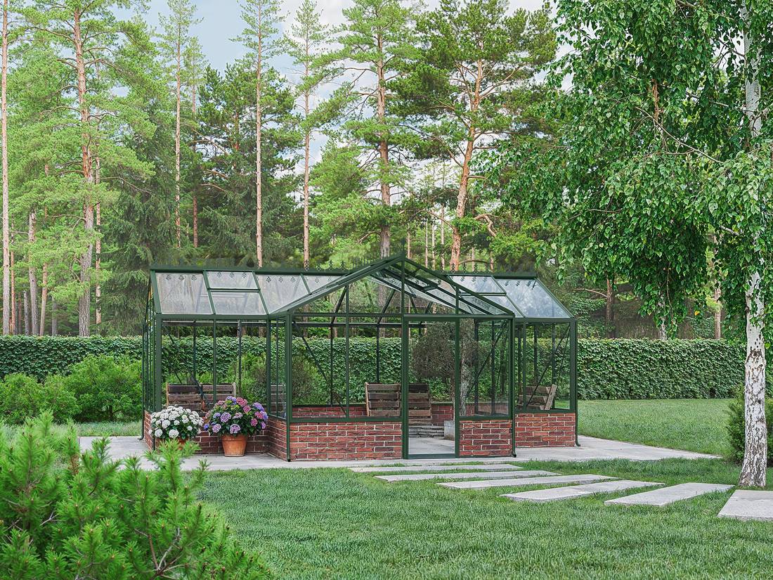
Treat the drawing as project information, not as a styled product picture. Its lines identify the space claimed by the structure, the points where parts connect and the clearances needed for the base, assembly and day-to-day access. Most layout errors come from treating a nominal size, outside dimension, foundation dimension and clear interior dimension as though they were interchangeable.
Build your decision from the full document set rather than one measurement. Compare the plan, elevations, enlarged details and assembly manual. If a critical dimension is ambiguous, obtain written confirmation before constructing the foundation—especially for an orangery, a T-shaped plan or a greenhouse joined to an existing wall.
Identify the drawing type first
The drawing type determines what you can see. A floor plan shows the greenhouse from above. It is useful for checking width, length, door position, building shape and foundation outline. A front, side or rear elevation shows heights, roof pitches, eaves, ridges and the arrangement of wall and roof bays. A section cuts conceptually through the building and can reveal clear internal heights or profile connections.
Exploded drawings and assembly steps serve another purpose: they explain component order, fixing points and orientation. Detail drawings enlarge individual junctions, such as the base, door threshold or wall profile. Perspective views help with spatial orientation, but are not normally a dependable basis for setting out.
Record the model name, variant, revision status and view shown on every document. On apparently symmetrical structures, a marked north arrow or a garden-side note helps prevent left and right from being reversed.
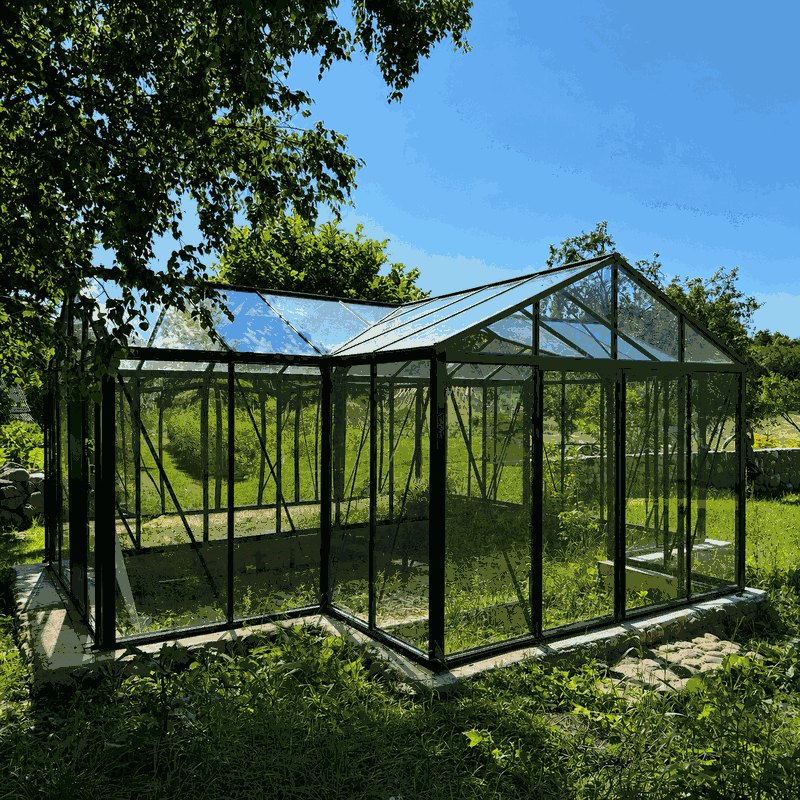
Understanding the main greenhouse dimensions
Overall width and overall length
Width and length can refer to different reference points: the outside of a profile, the outside of a base, the centreline of a structural component or the foundation edge. Dimension arrows and extension lines show which points are intended. If extension lines reach the outermost profile edges, the figure usually indicates an external dimension. If they end at an inset base, the drawing may show a base or bearing dimension.
For rectangular models, multiplying 2 values does not complete the space plan. Roof projections, downpipes, door travel and assembly access may extend beyond the stated footprint. Explore the available forms in Greenhouses and Conservatories. For design context on more complex structures, see the guide to orangeries, sizes and building forms.
Eave height, ridge height and overall height
Eave height is measured where the side wall meets the roof. Ridge height is the highest point of a conventional gable roof. An additional overall height may include further components. Always check the lower reference point marked on the drawing: finished top of foundation, ground level, underside of the base or another defined level.
Heights matter for more than headroom. They affect clearances from branches, gutters, wall projections and other site features. Open roof vents may also project beyond the closed building envelope. Plan for more than the closed view.
Door dimensions
Distinguish at least 3 measurements for a door: the rough or frame opening, the clear passage width and the outside size of the door unit. For wheelbarrows, potting benches or equipment, the clear passage opening is what matters. An outside frame measurement does not automatically show how much space is actually passable.
Also check the opening type and operating space. A hinged door needs clear swing room; a sliding door needs space beside the façade. Threshold height and the finished path construction can matter too. Consider the door alongside the outside path, internal route and foundation rather than in isolation.
Bay grids and glazing divisions
Many aluminium greenhouses are divided into repeating bays. Dimension chains may therefore show a centreline grid, individual panel widths or total length. Add partial dimensions only when they clearly use the same reference points. Profile widths or end bays can mean that assumed panel dimensions do not add up exactly to the external measurement.
The divisions are useful when planning accessories, vents, shelving and planting. They must not be treated as a freely selectable construction grid. Read about the material properties of multiwall panels in Polycarbonate in the Greenhouse. The technical documents for the specific model remain controlling.
Reading the language of dimension lines
Technical dimensioning usually consists of a number, a dimension line, arrows or end marks, and extension lines. Extension lines lead to the measured points. A continuous overall dimension describes the entire distance; a chain dimension divides it into sections. Bracketed or specially marked figures may be informational only, depending on the document. Do not rely on general assumptions: follow the legend for the drawing in question.
Symbols for diameter, radius, angle, slope or elevation each have a distinct purpose. Centre lines and hidden edges must not be confused with real external edges. If there is no legend, clarify every interpretation that affects construction.
Never measure from a screen or printout
Do not measure a PDF with a ruler against the screen. Zoom level, screen size and page fitting alter the display. A printout can also be reduced, enlarged or distorted automatically. Even where a scale is shown, the printed dimension takes priority unless the document says otherwise.
If the document says “not to scale” or uses a similar abbreviation, use only the stated dimensions. Do not derive a missing number by measuring the graphic.
Check units on every document
Check whether dimensions are given in millimetres, centimetres or metres. Technical product drawings often use millimetres, while site plans commonly use metres. Mixed documents increase the risk of errors. Keep units beside your own calculations and convert only at the end.
Decimal separators also require attention. Do not transfer values blindly into planning software or spreadsheets with different comma and point settings.
Nominal size, actual supporting footprint and usable interior
A size designation often helps classify a model. It does not have to match the external supporting footprint to the millimetre. The nominal size is therefore not automatically a foundation dimension. The actual supporting footprint describes the outline required for the base or support. The usable interior is further reduced by profiles, bracing, doors and interior fittings.
| Dimension type | Typical use | Check before work begins |
|---|---|---|
| Nominal size | Model comparison and sorting | Do not use directly for foundation construction |
| Maximum external dimension | Space requirements and clearances | Include projections and open components |
| Base or bearing dimension | Planning the structural support | Check reference edges and squareness |
| Clear internal dimension | Paths, benches and use | Allow for bracing and door areas |
Similar terms occur with other outdoor structures. The pergola size guide, the pergola foundation guide and the product page for the Elma S outdoor sauna show why product size, external outline and installation footprint should always be considered separately.
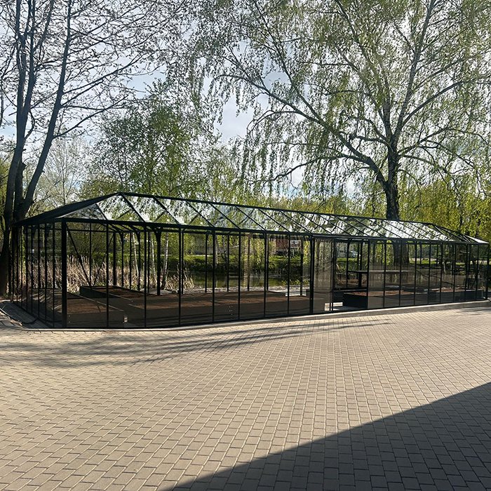
Break complex floor plans into separate zones
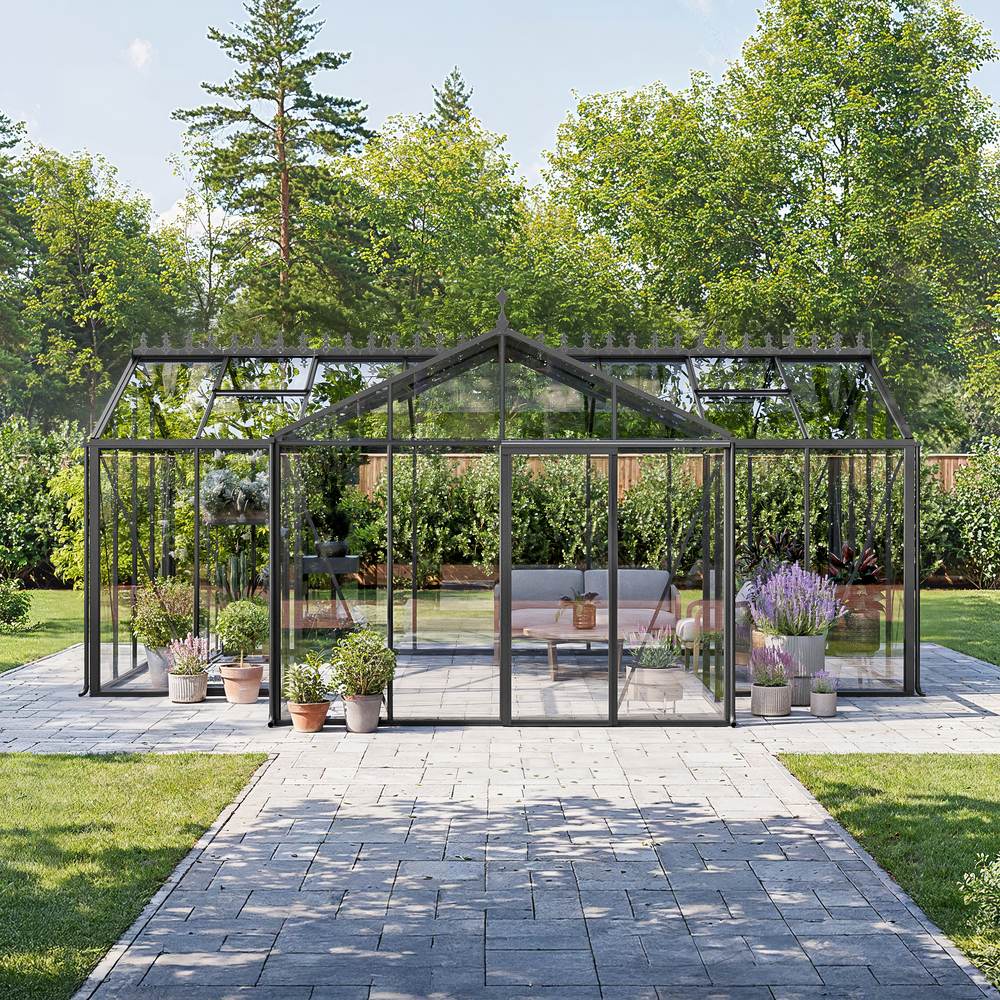
T-shaped structures, orangeries and designs with projections are easier to assess when the floor plan is divided into rectangles and connection zones. Mark the main body first, then each cross wing, entrance area and recess. Record the width, length and position relative to the shared axis for every zone.
- Mark the outermost overall outline.
- Add main axes and lines of symmetry.
- Dimension each partial area separately.
- Count and mark inside and outside corners.
- Check dimension chains against the overall dimension.
- Add the door and circulation zone.
A plan may contain mathematically plausible partial dimensions yet still be oriented incorrectly on the site. Set one unambiguous reference side, such as “house side” or “garden gate”. Historically inspired ideas from the article on Victorian greenhouses should be considered only after this technical groundwork.
Transfer the drawing to the installation site
Establish a fixed reference line rather than placing 4 points independently. It could be a building line, string axis or accurately surveyed baseline. Set the other points square from that line, and mark the structure outline and foundation outline in different colours.
Before work begins, establish which requirements apply at the property. In Canada, start with the province or territory and the municipality: the NRC's National Model Codes do not, by themselves, establish the rules in force everywhere. Permit, zoning and other site requirements must be confirmed for the location and proposed structure. The article Do You Need a Permit for a Greenhouse or Pergola? is a useful first check, but confirm the current requirements with the authority responsible for the property.
Check more than 4 corners
On long or segmented layouts, checks cannot stop at the 4 corners. Verify intermediate axes, the door opening, recesses and connection points. Measure both diagonals and confirm the side lengths as well. Equal diagonals establish a rectangle only when the other geometric conditions are satisfied; they do not show that the base is level or flat.
Check slopes, high points and changes in level as well. A correct horizontal outline can still cause assembly problems on uneven ground.
Set out a full-size model where space is tight
String, marking spray or boards laid flat make the space requirement immediately visible. Test the ridge or eave area with a ladder or cardboard marker. Open garden gates and simulate the route with a wheelbarrow. This can expose conflicts that remain hidden in a small floor plan.
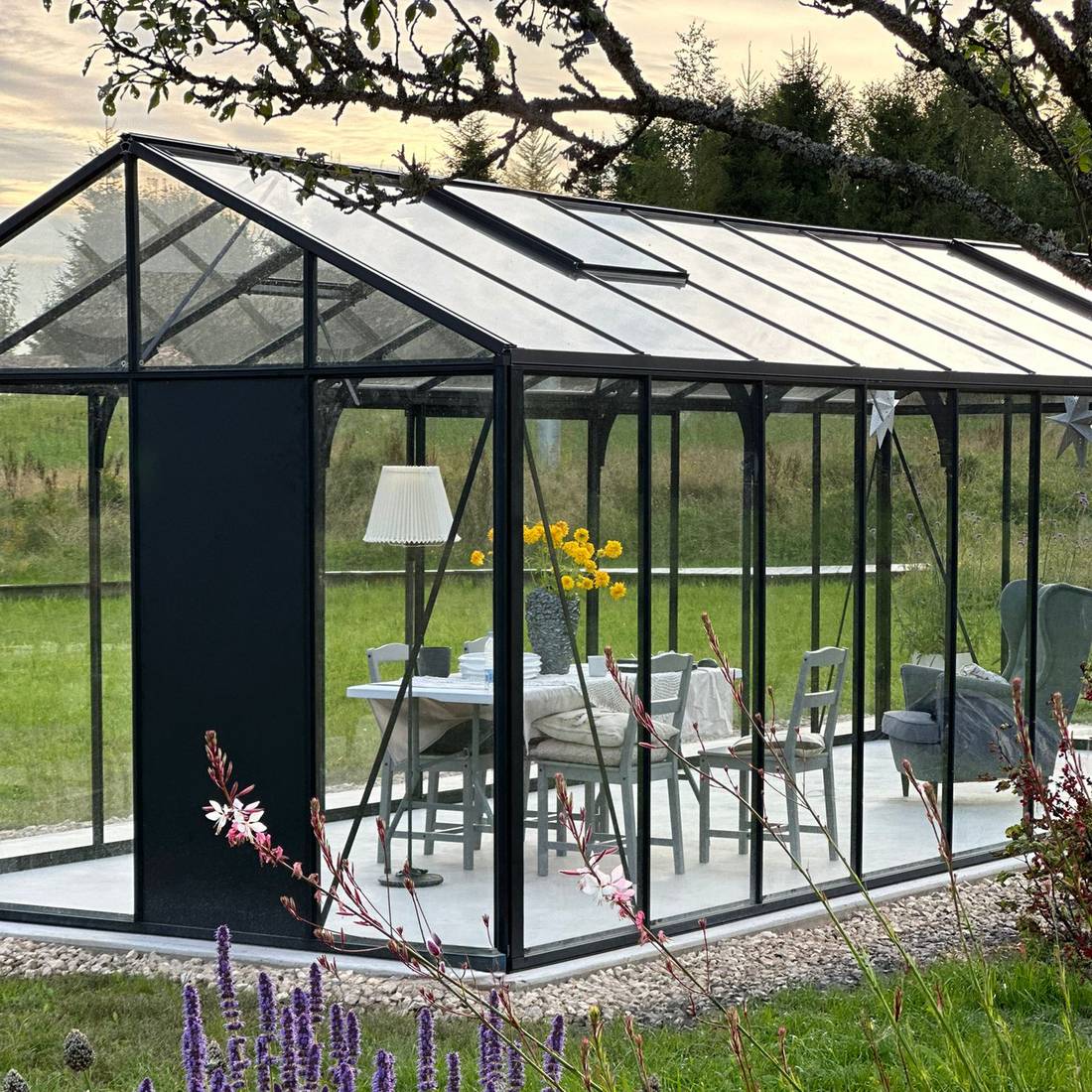
Drawings for lean-to and wall-mounted greenhouses
With a lean-to greenhouse, the existing wall has an important geometric and structural role. In addition to width and depth, you need the attachment height, roof pitch, wall-profile positions and clearance from windows, pipes, roof projections and drainage.
Assess the wall over the full connection length. Base projections, uneven render or sloping surfaces can prevent a profile from sitting flat. Suitability and structural capacity of the wall construction must be assessed for the specific project. A related distinction appears in the comparison Wall-Mounted or Freestanding Pergola. Find further design differences in Bioclimatic or Classic Pergola.
Plan the interior using clear dimensions
Clear widths govern practical use. Do not simply subtract an assumed profile thickness from the external dimension. Use stated internal dimensions or have critical clearances confirmed. Plan the main path, secondary paths, work areas, planters and door zone separately.
Tall crops do not need ridge height everywhere. Available height reduces towards the side wall beneath a sloping roof. Shelving must not block vents, bracing or gutters. For use-focused planning, see Growing Lettuce in a Greenhouse and Temperature and Humidity. The structure must remain accessible in accordance with assembly and maintenance instructions.
Use documents in the right order
Review the locally displayed assembly-manual library early. A sensible working sequence is:
- Confirm the product variant and order scope clearly.
- Read the technical overview drawing for the external outline and heights.
- Identify the foundation or base drawing.
- Check the assembly manual for the base, door orientation and connection details.
- Compare the current document revision with the documents supplied.
- Resolve open dimensions before building elements that are difficult to alter.
If two documents differ, do not choose the value that merely looks more plausible. Record the model, document title, revision status and affected dimension, then contact us. General help is available under Useful Information.
Checks on delivery and before assembly
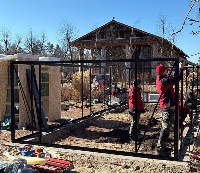
Before installation, compare the model name, package count against the delivery documents and visible component labels. Open or store packages only in line with the supplied instructions. A floor plan can be prepared correctly while a different variant or door configuration has been delivered or selected.
- Do the model and variant match the order?
- Does the door position match the approved plan?
- Is the foundation complete, level and dimensionally checked?
- Are all necessary access areas available?
- Have connection details and drainage routes been resolved?
- Is the correct assembly manual available?
Practical ordering information is available under Purchase and Delivery and How to Order. For deliveries across Canada, including territories and islands, see greenhouse delivery information .
Common mistakes when reading drawings
- Using the model name as a foundation dimension: A rounded size description is not a construction dimension.
- Reading only one view: A floor plan and side elevation answer different questions.
- Confusing external and internal dimensions: Paths or work areas become too narrow.
- Ignoring door movement: The opening later conflicts with a bed, fence or step.
- Planning a mirror image: A perspective image is mistakenly read as a binding door orientation.
- Measuring from a PDF: Zoom and print scaling create incorrect values.
- Mixing units: Millimetre values are transferred as centimetres or metres.
- Checking diagonals only: Level, side lengths and intermediate points remain unchecked.
- Forgetting maintenance space: External surfaces and drainage later become inaccessible.
Find advice on long-term access in Maintaining an Aluminium Greenhouse. Experiences from other buyers in Greenhouse Reviews may offer practical perspectives, but do not replace a model-specific drawing.
Questions before approving the greenhouse layout
- Has the exact model and equipment variant been confirmed?
- Which line marks the maximum external dimension, and which marks the base?
- From which height level are the eave and ridge measured?
- Where is the clear door opening, and how does the door move?
- Is the structure correctly oriented on the site plan?
- Are outside clearances available for assembly, cleaning and drainage?
- Have wall projections, trees, services and site slope been recorded?
- Do the partial dimensions, overall dimensions and diagonals agree?
- Has the foundation solution been confirmed for the model and site?
- Have local requirements been checked before work begins?
Frequently asked questions
Are listed greenhouse dimensions internal or external?
Do not assume without an explicit label. Product overviews often give nominal or external dimensions, while technical drawings may also include base and internal dimensions. Follow the dimension arrows, reference lines and legend for the specific document.
Can I build the foundation from the dimensions on the product page?
Not without checking the model-specific foundation, base or assembly drawing. A product page is primarily for selection. Have critical dimensions confirmed before building concrete, masonry or other elements that are difficult to change.
Why does the nominal size differ from the technical drawing?
Nominal sizes make a model range easier to classify and may be rounded. A technical drawing instead describes specific reference points. Profiles, bases and structural divisions can result in different actual dimensions.
What does “not to scale” mean?
The drawn length must not be determined with a ruler or screen tool. Use only the stated dimensions. If a needed measurement is missing, request it.
How can I tell which side the door is on?
Use the floor plan and look for the door symbol, opening direction or component label. Also define from which side the building is viewed. If the variant can be mirrored or the view is unclear, confirmation is needed.
Which dimensions matter for a lean-to greenhouse?
In addition to width and depth, check wall-connection height, eave level, highest roof edge, roof pitch, profile position and clearances to existing components. Wall flatness and the structural suitability of the support must also be assessed.
How much extra space should I leave around it?
There is no single figure for every model and property. The required room depends on assembly, cleaning, open windows, drainage, paths and local setback requirements. Plan a genuinely usable working and maintenance area, then check applicable municipal and provincial or territorial requirements.
Do equal diagonals prove that the foundation is correct?
Not completely. Equal diagonals are an important check for a rectangular footprint, but must be assessed alongside side lengths, intermediate dimensions, flatness and level. For complex forms, check each zone separately.
Which document applies when two dimensions differ?
This cannot be decided simply by document type. Check the model assignment and revision status, then have the controlling value confirmed by the supplier. Do not alter the foundation until the issue is resolved.
Where can I find warranty and maintenance information?
The terms are available in the Warranty section. Review maintenance guidance separately, as dimensioned drawings, assembly manuals and maintenance information serve different purposes.
Final drawing check
Carry out the final review not only at a desk, but also at the marked-out site. Compare the model, document revision, external outline, base dimension, heights, door, diagonals and connection zones. Then test use: can the door operate fully? Do paths remain passable? Can roof vents, gutters and outside surfaces be reached?
A dependable plan emerges only when the same reference points are used in the product documents, foundation drawing, assembly manual and site set-out.
Record approved dimensions in a simple checklist and photograph the site set-out. This keeps the planned variant traceable. For further ideas on using your greenhouse, visit the Bloomcabin Blog; technical decisions should always be based on the documents for the selected model.
