



Electrical Planning for a Motorized Pergola: Louvres, Controls and Lighting
Plan the wiring while the pergola exists only as lines on a site drawing—not after the posts and patio finishes are in place. This guide explains what to collect before rough-in, how to align power and control routes, and how to leave practical access for lighting, commissioning and later additions.
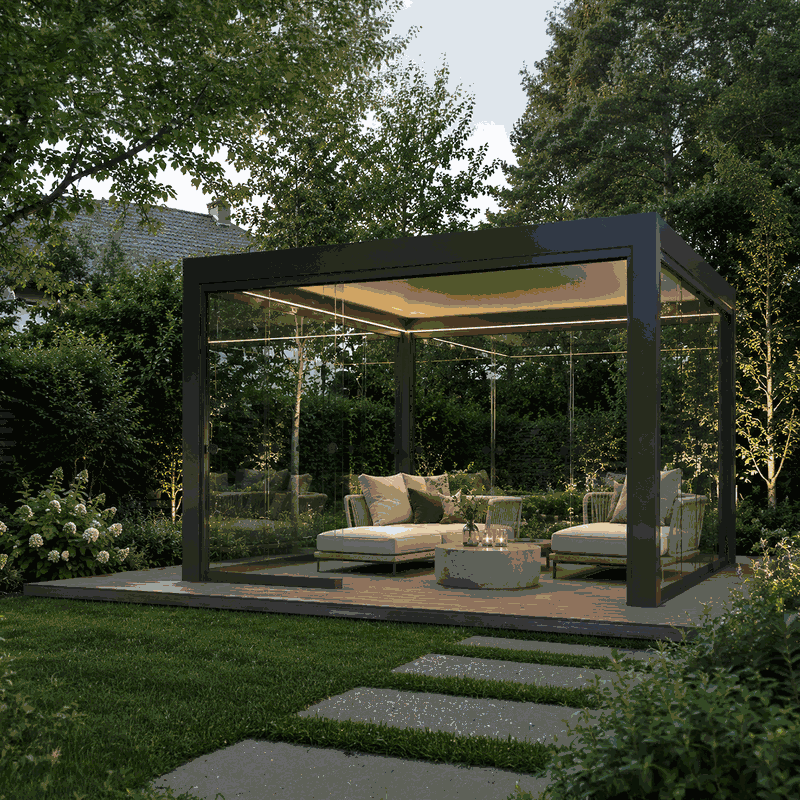
Posts, foundations, roof drainage and wiring all compete for space within the same project area. If cable routes are decided after assembly, wiring may remain visible, finished components may need drilling, and connection points can become difficult to service. Bringing the owner, pergola installer and electrical contractor together early avoids many of these conflicts.
This article is a coordination checklist, not a substitute for the model-specific technical documents or the work of a qualified local electrical contractor. Before installation, confirm the electrical ratings, protective measures and any local permit, inspection or equipment-acceptance steps for the actual project.
Which parts of a motorized pergola need power?
The louvred-roof drive is the most obvious electrical load. Depending on the system, power may also be needed for a controller, receiver, power supply, wall switch, integrated lights or optional sensors. Handheld remotes generally operate independently of the fixed installation, but require a compatible receiver at the pergola.
Not every bioclimatic pergola uses the same electrical layout. A motor may run directly from the supply, through a separate power supply or via a manufacturer-specific controller. The outside appearance alone does not establish voltage, cable type or connection method.
- Louvre drive: moves the roof louvres and requires a clearly assigned supply.
- Controls: process signals from switches, remotes or compatible sensors.
- Lighting: may be integrated, surface-mounted or installed independently of the pergola.
- Optional equipment: such as sensors or later side-wall options with powered components.
Information to settle before electrical rough-in
Select the exact pergola model before cutting channels in walls, drilling or laying underground cable. First use the guides on the choice between a bioclimatic and a classic pergola, wall-mounted or freestanding installation and the pergola size concept help clarify the structural basics first.
| Required information | Why it matters |
|---|---|
| Exact model and configuration | Determines the motor, controls, possible lights and intended connection locations. |
| Orientation and post positions | Determines where cables can emerge without interfering with foundations or drainage. |
| Motor and control side | Prevents the supply from being prepared at the wrong end. |
| Manufacturer electrical documentation | Lists the required connection method and compatibility details. |
| Preferred operating locations | Affects cable routes for switches, controls and, where needed, additional switching points. |
| Lighting and expansion plans | Allows sensible provision for later work without adding unused equipment. |
The planned pergola range and its current installation manual must be matched to the project precisely. Product photographs and generic sketches are not adequate for electrical rough-in.

Coordinate the structure, drainage and wiring on one site plan
Base the cable plan on the same dimensioned drawing used for foundations and assembly. Mark the building supply, pergola axes, posts, foundation blocks, patio build-up, drainage direction, cable routes and exit points together. The guide to pergola foundations shows why the supporting base must be resolved before assembly begins.
Cables must not obstruct fixing zones or emerge without control where water drains from the roof system. A conduit should not end where it could be crushed by a post or struck by fixings. For existing patios, take account of build-up height, waterproofing and possible movement joints.
Before work starts, identify the rules adopted for the property. Canada’s national model codes do not create one permit process for every location. Use the localized pergola permit guide as an initial checklist, then confirm the project with the province or territory and municipality responsible for the site.
Electrical routes for freestanding and wall-mounted pergolas
Freestanding pergola
For a freestanding structure, the supply is often run underground to a preselected post. The electrical contractor must determine the route, burial depth, mechanical protection, cable type and entry method for the installation conditions. A conduit is useful only when its size, bend radius, sealing and final position suit the intended cable.
The cable exit must align exactly with the assembly drawing. A generously estimated point within a foundation zone may later sit beneath a base plate or outside the post profile. For structural context, see the freestanding Bloomcabin pergola.
Wall-mounted pergola
With a wall-mounted pergola , the supply may come from the building. Even so, the shortest route is not automatically the best one. Insulation, wall construction, waterproofing, structural elements and the wall-fixing positions all need consideration. Wall penetrations must be properly sealed against moisture.
Before the route is installed, establish which side contains the motor or controls. The specific wall-mounted pergola configuration is decisive. Do not place a cable solely from a perspective product image.
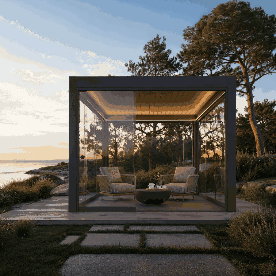
Design the supply around the actual equipment
The electrical contractor must assess the connected load, cable length, installation method, environmental exposure, protective measures and existing distribution panel. Those project details determine conductor size, overcurrent and ground-fault protection, and whether a dedicated circuit is useful or required. Generic values are unreliable because the pergola model, accessories and building installation can differ.
Motor and lighting may be supplied together or separately if the product documentation and electrical design allow it. Separate circuits or independently switched outputs can simplify fault-finding: a lighting fault need not stop the roof drive. An unnecessarily complex installation, however, should not be created without a clear benefit.
An existing outdoor receptacle does not automatically prove that the supply is suitable. Its condition, protective measures, loading and circuit assignment must be assessed. Temporary extension cords are not a substitute for a planned permanent outdoor installation.
Separate power and control cabling deliberately
Do not treat cables carrying different voltages or signal types as interchangeable. The actual system and applicable requirements determine separation, enclosures and cable types. Improvised joints between manufacturer-specific motor leads and building wiring are especially unsuitable.
Label every cable clearly and permanently at both ends. Photographs of open routes and a drawing with reference points are also useful. If conduits are provided, do not leave them unlabelled at several posts. A pull wire can help with later work, but does not prove that the route is usable.
Location of the louvre motor and controls
The motor, junction box and control unit must remain accessible without being permanently exposed or unprotected. Service access does not mean components must be open without tools. It means a qualified person can reach them without unnecessarily removing structural parts, roof louvres or permanently fitted cladding.
Install controls only in a location and orientation approved by the manufacturer. Consider water paths, condensation, direct weather exposure and heat build-up. For a motorized Bloomcabin pergola , model-specific documents take priority over general installation habits.
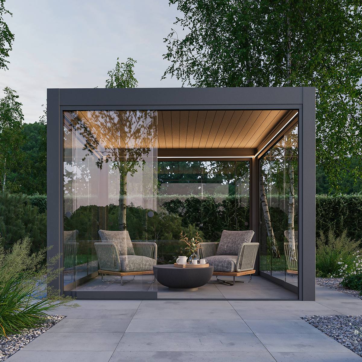
Design lighting around how the pergola will be used
Lighting is both an electrical and a design decision. It should make seating and walking areas useful without causing glare or distracting reflections on glazing. Find different use ideas in the pergola ideas for patios and gardens.
Integrated lights must be intended for the exact pergola system or expressly confirmed as compatible. Drilling into frame profiles can disrupt drainage, finishes or concealed cable channels. Surface-mounted additions also need suitable fixings and a supply designed for their outdoor location.
Questions before choosing a lighting layout
- Should the light mainly illuminate a table, walking routes or the whole roof area?
- Is one shared switch needed, or several lighting zones?
- Where could reflections occur on windows or future glass walls?
- Where can power supplies or control components be kept accessible?
- Should operation use wall switches, compatible remote controls or existing building controls?
- Can lighting still be operated independently when the louvre drive is switched off?
Anyone comparing a fixed roof with a movable one should also consider the guidance on a bioclimatic louvred roof and glass roof . Roof type and lighting design influence each other.
Leave useful options for later—without guessing
A practical allowance might be an accessible conduit, a recorded cable route or reserved space in a suitable connection area. Do not permanently connect unidentified future loads. Accessories selected later may use different voltages, control protocols or connection positions.
Planned glass walls deserve particular attention. The guide to sliding and fixed glass walls for pergolas shows the structural differences. Cable exits, switches and service openings must not fall in future movement routes or fixing zones.
A practical order of work
- Define use and pergola type: choose size, installation type, roof function, lighting and any future side walls.
- Survey the site: document the building, levels, patio build-up, foundations, drainage and existing services.
- Review product documentation: confirm the motor side, electrical ratings, control components and intended cable entries.
- Create a coordinated trade plan: the pergola installer, foundation contractor and electrical contractor use the same dimensions and reference points.
- Prepare cable routes: install routes and penetrations professionally, mark them and photograph them before they are concealed.
- Complete foundations and surfaces: protect cable ends and compare their position again with the assembly drawing.
- Assemble the pergola: run cables only through designated areas; do not make unplanned profile drillings.
- Make electrical connections: the electrical contractor carries out testing, connection and documentation for the specific system.
- Commission functions: check motor movement, controls, lighting and shut-off options.
For basic product selection, consult the practical guide to aluminum pergolas and the overview of Bloomcabin pergolas .

What to verify before installation day
- The delivered model, configuration and documentation match the plan.
- Components are stored dry and safely without blocking the work area.
- The post side and motor side are marked on the site plan.
- Foundations and fixing surfaces are ready for installation and have been checked.
- Cable exits are within the intended connection area.
- Cable ends are protected, de-energized and clearly labelled.
- Connection and control components have been fully identified.
- The electrical contractor knows the planned date for testing and final connection.
- Drilling, assembly and service areas remain freely accessible.
If anything remains uncertain, use the Bloomcabin contact page before assembly. Resolving a discrepancy early is less disruptive than relocating completed work.
Commission the roof drive, controls and lights
Before the first motor run, check the louvre movement area for tools, packaging or fixing materials. Electrical testing comes before functional testing. Then move the roof gradually and observe smooth operation, correct end positions and any unusual sound.
Pair remotes and wall controls in line with their instructions, then test each command individually. For lighting, test zones, dimming and shutdown behaviour only where these functions are actually provided. Activate sensors only once their location, assignment and response have been clearly confirmed.
If the drive jerks, makes unusual noise or moves in an unexpected direction, do not keep operating it. Switch off the supply and have the assembly, wiring and settings professionally checked.
Maintenance and troubleshooting
Electrical components need visual inspections, especially after construction work, severe weather or changes to the patio. Look for visible damage, loose covers, signs of moisture and crushed cables. Keep aluminum profiles and drainage routes clean; general care principles are explained in the guide to caring for aluminum structures.
When a fault occurs, first establish whether it affects only the motor, only the lights or the whole system. Then check the control device, visible shutdown states and obvious obstructions. Unqualified persons must not open electrical enclosures. The article on using a pergola in winter covers seasonal use and weather considerations.
Coordinate the pergola with other Bloomcabin structures
Where several garden structures share one property, prepare an overall site and services plan. This may include a pergola, greenhouse or conservatory, garden house and an outdoor sauna. Shared routes can make planning sense, but do not mean every load may use the same circuit.
A sauna, such as the Elma S outdoor sauna, has a different purpose and electrical design from a louvre drive. Plan each structure from its own documentation. Information about the company and product range is available under About Bloomcabin and in the Useful Information section.
Pergola electrical planning: common questions
Can an electrician prepare the supply before the pergola is delivered?
Yes, if approved documents for the exact model are available. The motor side, connection location and electrical data must be confirmed. Otherwise, take the cable only to an accessible handover point.
Can an existing outdoor receptacle be used?
Only after professional assessment. The receptacle, supply cable, protective measures, existing load and suitability for permanent use must be evaluated. Its proximity to the pergola is not enough.
Does every louvred pergola use the same motor voltage?
No. Motor, power-supply and control concepts differ. Only the documents and markings for the delivered system are authoritative.
Should the motor and lighting be on one circuit?
That depends on connected loads, the control concept and the local installation. Separation can improve operation and fault-finding, but the electrical contractor must determine it for the project.
Can a cable be concealed in a pergola post?
Only if the specific system provides a suitable cable route. Drainage, fixings, sharp edges and service access must not be affected. Avoid unplanned drilling into profiles.
Can lighting be added later?
Retrofitting may be possible. It is easier when an accessible cable route has been prepared. Lights and fixings must be compatible with the pergola, outdoor conditions and electrical installation.
Where should a wall switch be installed?
Choose an accessible, suitable location from which roof movement can ideally be observed. Consider weather exposure, building use, child access and future glazing when positioning it.
Can the pergola be operated when it is out of sight?
Unobserved movement can mean that people or obstacles are missed. Follow the intended operating method and all manufacturer safety information. Remote operation does not automatically make every operating location suitable.
What changes if glass walls are installed later?
Movement routes, fixing zones, switch access and reflections may change. Cables and junction boxes must not obstruct the glass system. Include the future addition in the site plan from the outset.
Who may make the final electrical connection?
Use a qualified local electrical contractor for the permanent connection and required testing. Ask the local authority and contractor what permits or notifications, inspections and equipment-acceptance checks apply to this installation.
Which documents should be kept?
Keep assembly and electrical instructions, the model designation, circuit or cable plan, test documents, photographs of concealed routes, labels and records of later changes. Everything should be clearly associated with the same installation.
What should be done if the documentation and rough-in do not match?
Stop assembly or connection at that point. Clarify discrepancies with the supplier, installer and electrical contractor. Do not make a cable fit using improvised extensions or unverified adapters.
Final coordination check
- The exact pergola model and orientation are defined.
- Motor, control and lighting data are available in writing.
- Foundation, drainage and cable routes are coordinated on one plan.
- The supply terminates at the confirmed connection location.
- Line-voltage, control and signal cables are correctly assigned.
- Service access remains available after assembly.
- Future glass walls or electrical additions have been considered.
- All cables and switching points are documented and labelled.
- Final connection, testing and commissioning are arranged with an electrical contractor.
A well-planned electrical installation should fade into the finished pergola while leaving clear access for maintenance and systematic troubleshooting. More technical and design guidance is available in the Bloomcabin Blog and Useful Information section.
