



MATERIALS
Greenhouse Drawings Explained: Dimensions and Site Layouts
Use this guide to work methodically through greenhouse plans, elevations, measured details and assembly documents. Before ordering or building, verify the frame outline, supporting base, entrance, heights, usable interior and every wall connection.
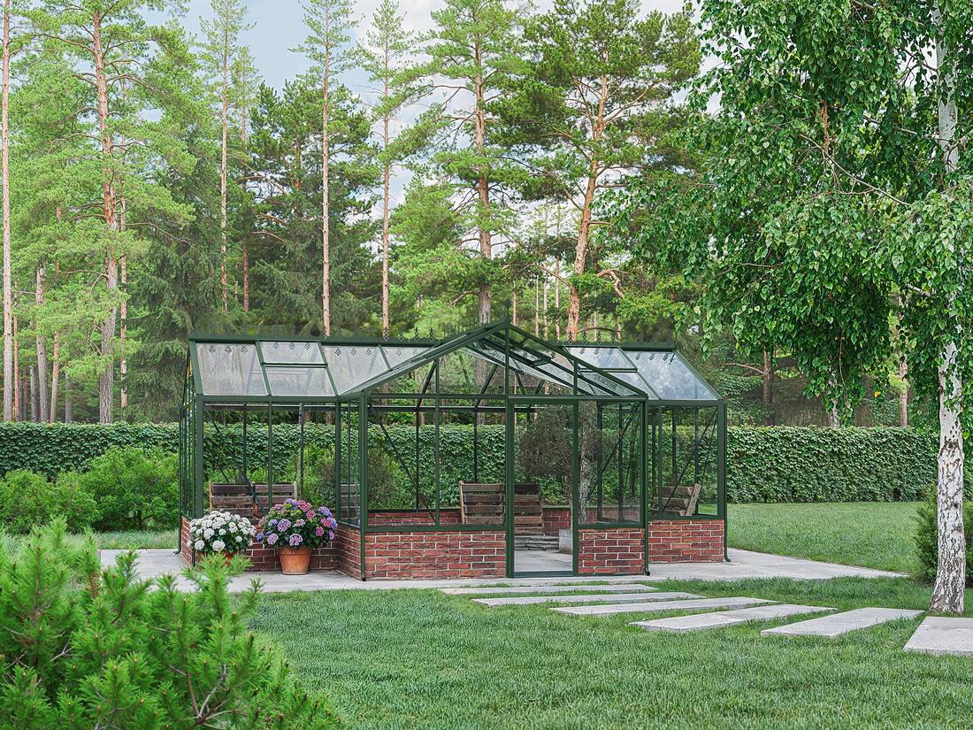
A greenhouse drawing presents project information, not a styled image. It defines the occupied area, component junctions and clearances for the base, assembly and later use. Errors usually arise when nominal size, outside dimensions, foundation dimensions and clear interior space are treated as equivalent.
Do not rely on one dimension. Read the plan, elevations, details and assembly instructions as one document set. If anything is unclear, obtain written confirmation before building the foundation, particularly for large orangeries, T-shaped layouts and models joined to an existing wall.
Establish the viewpoint before reading dimensions
What a sheet can tell you depends on its viewpoint. The plan view looks down on the greenhouse, revealing its width, length, entrance location, form and base outline. A front, side or rear view records vertical levels, roof angles, eaves, ridges and the pattern of wall and roof bays. A sectional view imagines a cut through the structure, exposing headroom or relationships between profiles.
Exploded views and assembly stages show part sequence, fixing points and orientation. Enlarged details focus on junctions such as the base, threshold or wall profile. Perspective images help visualise the form, but normally should not control setting out.
Note the model, configuration, revision and viewpoint on each sheet. Where a structure looks symmetrical, add a north arrow or label the garden-facing side so that left and right cannot be accidentally exchanged.
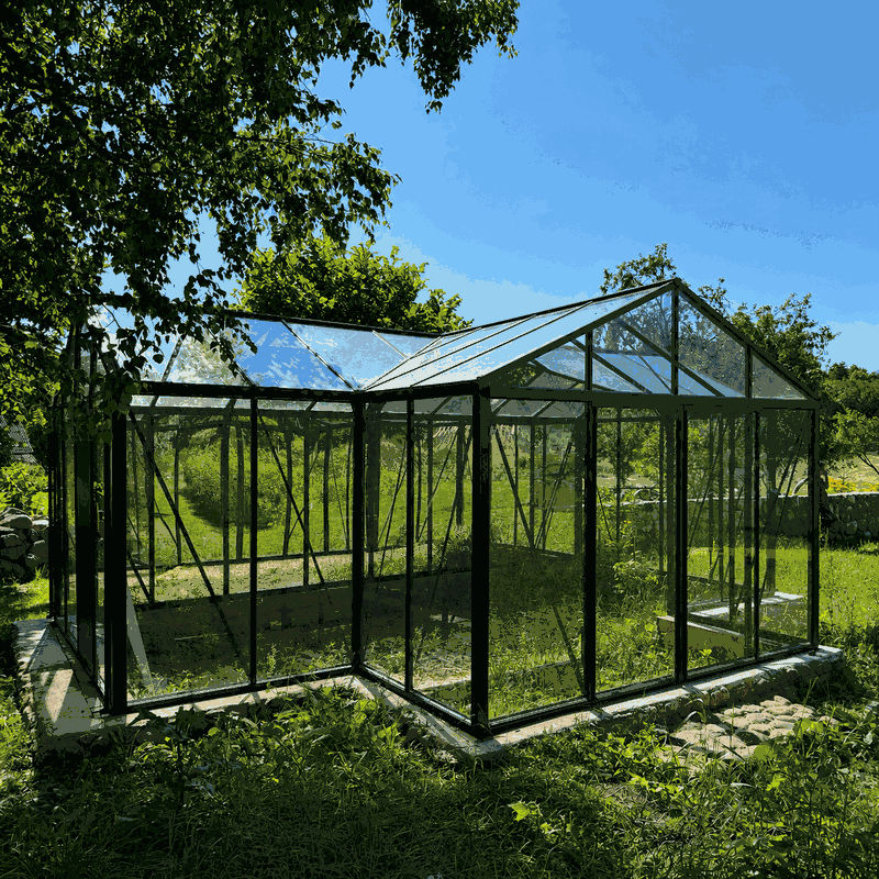
Recognising the essential greenhouse measurements
Full width and full length
Width and length may be measured between outer profile faces, base edges, structural centrelines or foundation edges. Use arrows and projection lines to find the endpoints. Lines reaching the outermost profiles usually indicate an external dimension; those ending at a recessed support may show a base or bearing dimension.
Even on a rectangular model, multiplying width by length does not describe every space requirement. Eaves, downpipes, a moving door and installation access may project beyond the marked footprint. Compare available shapes under Greenhouses and Conservatories. More elaborate layouts are discussed in the article covering orangery forms and size choices.
Eaves, ridge and highest overall point
Eaves height is measured where side wall meets roof; ridge height reaches the top of a conventional pitched roof. A separate overall height may include extra fittings. Check the lower datum shown: finished foundation surface, ground level, base underside or another defined reference.
Height affects more than headroom. Branches, gutters, masonry projections and other site features may obstruct the structure. Open roof vents can extend beyond the closed envelope, so assess both positions.
Measurements around the entrance
Door drawings may distinguish the structural or frame opening, clear passage and complete door unit. For a wheelbarrow, bench or equipment, the unobstructed entrance width matters; the frame’s outer size does not show the space available.
Check the opening method and travel area. A hinged door needs a clear arc; a sliding door needs space along the façade. Threshold height and the finished path can affect access. Consider the door with the outside route, interior route and foundation.
Structural bays and glazing patterns
Aluminium frames often use repeating bays. A dimension chain may show centrelines, individual panes or total length. Add partial measurements only where the endpoints follow the same convention. Profile widths and end bays can stop assumed panel dimensions from matching the external measurement exactly.
The pattern can assist with shelves, ventilation, accessories and planting positions, but it is not an interchangeable construction module. For background on multiwall glazing, consult Greenhouse Polycarbonate Explained. For an individual model, its issued technical documents take precedence.
How to follow a chain of dimensions
Technical dimensions usually combine a number, dimension line, arrows or end marks, and projection lines to the measured points. An overall line spans the full distance; a chain divides it into sections. Bracketed or specially marked values may be informative only. Check the drawing’s legend rather than assuming a universal convention.
Diameter, radius, angle, gradient and level symbols communicate different properties. Dashed hidden edges and centrelines are not physical outside faces. If no key is provided, obtain clarification for any interpretation that could alter the work.
Do not scale a monitor image or ordinary print
Do not measure a PDF with a ruler on the screen. Zoom, monitor size and page fitting alter its appearance; printing can also resize or distort it. Unless the document says otherwise, use the stated dimension rather than a length taken from the image.
When marked “not to scale”, or with an equivalent abbreviation, rely only on stated dimensions. Ask for any missing measurement instead of deriving it from the image.
Confirm the measurement unit sheet by sheet
Check whether each document uses millimetres, centimetres or metres. Product drawings often use millimetres, while site plans may use metres. Mixed documents increase error risk. Keep units beside every calculation and convert only at the end.
Check decimal notation too: software with different language settings may interpret points and commas differently.
Model label, bearing outline and practical room inside
A size name often places a greenhouse within its range rather than defining the support outline exactly. Its catalogue size cannot therefore be assumed to specify the foundation. The bearing footprint sets out the perimeter needed by the base or other support, while the clear space within is reduced further by framing, braces, entrances and fittings.
| Type of measurement | What it helps establish | Verification needed before construction |
|---|---|---|
| Catalogue or nominal size | Comparing and grouping models | Never transfer it straight to the foundation |
| Furthest outside extent | Overall fit and surrounding clearance | Include projections and parts in their open position |
| Base or bearing outline | Setting out the supporting structure | Verify its datum edges, dimensions and squareness |
| Unobstructed internal measurement | Circulation, benches and intended activities | Account for braces, tracks and entrance areas |
The same distinction matters for other garden structures. Compare the guide to choosing a pergola size, the advice on pergola foundations and the listing for the Elma S outdoor sauna to see why a product’s named size, furthest outline and required support area must be assessed independently.
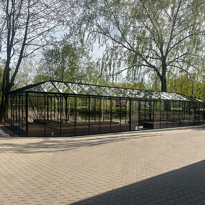
Analyse an irregular plan zone by zone
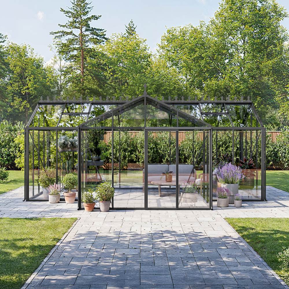
For an orangery, T-shape or projecting design, split the plan into rectangles and junction zones. Mark the main body, then each cross-wing, entrance and recess. Record every zone’s width, length and position against a common axis.
- Trace the furthest perimeter first.
- Draw in centre axes and symmetry references.
- Record each zone’s dimensions independently.
- Identify every internal and external corner.
- Reconcile the chained figures with the full extent.
- Mark the entrance and route through it.
Partial dimensions can add up while the plan still faces the wrong direction on site. Set an unambiguous reference side, such as “house” or “garden gate”. Consider ideas from Victorian-style greenhouses only after fixing this technical orientation.
Set the drawing out on the actual site
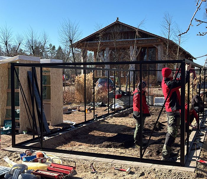
Start from one fixed baseline, not four independently placed corners. Use a building line, taut string or accurately surveyed datum, then set the remaining points square to it. Mark frame and foundation outlines in different colours.
Before permanent work, check the proposal with the relevant Irish planning authority. Permission or exempt-development status depends on the structure, use, property and site constraints. The article Irish Planning Checks for Greenhouses and Pergolas introduces the questions to raise, but project-specific confirmation remains essential.
Verify intermediate points, not merely the corners
For long sides or articulated plans, four corners are insufficient. Check intermediate axes, entrances, recesses and junctions, then measure both diagonals and side lengths. Equal diagonals indicate squareness only where the geometry permits; they do not confirm level or flatness.
Also check falls, high points and level changes. A correct plan outline may still sit on ground unsuitable for assembly.
Mock up the complete footprint in a restricted garden
Mark the full footprint with string, removable paint or flat battens. Use a ladder or cardboard marker to indicate eaves or ridge height. Open nearby gates and test the route with a wheelbarrow to reveal conflicts hidden on a small plan.
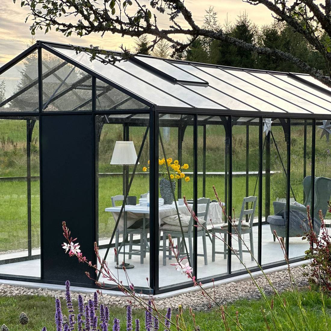
Plans for lean-to models and wall-fixed frames
For a lean-to greenhouse, the existing wall affects both geometry and structure. Besides width and projection, establish connection height, roof pitch, wall-profile position and clearances from windows, pipes, eaves and drainage.
Inspect the wall along the entire connection. A projecting plinth, uneven render or sloping surface may prevent the profile sitting flat. The wall build-up and load capacity need project-specific assessment. Similar distinctions are explained in Choosing Between Wall-Fixed and Freestanding Pergolas. Another relevant comparison is Classic Pergolas Versus Bioclimatic Designs.
Design the interior from unobstructed measurements
Usable layouts depend on clear widths. Do not subtract an assumed profile depth from an outside dimension. Use stated internal measurements or confirm critical gaps. Plan the main aisle, side routes, worktops, containers and doorway separately.
Tall crops do not need ridge height everywhere. Headroom falls towards the walls beneath a pitched roof. Keep shelves clear of vents, braces and gutters. For practical growing layouts, see Planning Lettuce Crops Under Glass together with Managing Greenhouse Temperature and Humidity. Continue to preserve the access required by the assembly and care instructions.
Consult the project documents in a deliberate order
Open the local assembly-document library early and work through the material as follows:
- Identify the ordered model, options and included components.
- Use the overview sheet to establish outside limits and vertical levels.
- Locate the dedicated base or foundation information.
- Review instructions for support details, door orientation and junctions.
- Match the latest document reference against the supplied paperwork.
- Clarify uncertain measurements before creating permanent or costly work.
When documents conflict, do not select whichever figure appears most convincing. Note the model, sheet title, revision and exact location of the discrepancy, then use the contact page. Broader customer guidance appears in Useful Information.
Delivery checks to complete ahead of assembly
Before assembly, compare the model, package count in the delivery documents and visible part labels. Open and store packages only as instructed. A correctly prepared plan cannot compensate for a different model variant or door configuration.
- Is the delivered configuration the one ordered?
- Does the entrance correspond with the agreed layout?
- Has the finished support been checked for size and level?
- Can every required working area be accessed?
- Are the junction and water-discharge routes settled?
- Do you have the manual for this exact model?
Ordering guidance can be found under Purchasing and Delivery and Ordering from Bloomcabin. For greenhouse orders anywhere in Ireland, islands included, consult delivery details for Irish customers .
Drawing-reading errors that lead to site problems
- Treating a model label as the base size: Rounded catalogue terminology is not a setting-out measurement.
- Consulting a single viewpoint: Plans and elevations reveal different aspects of the structure.
- Substituting outside size for clear space: The resulting aisles or work zones may be unusably narrow.
- Omitting the door’s operating area: Its travel may meet a raised bed, boundary or step.
- Reversing the proposed orientation: A perspective illustration is mistaken for the approved entrance arrangement.
- Taking measurements directly from a PDF: Display magnification and printer settings distort the result.
- Transcribing figures without their units: Values in millimetres may be misread as centimetres or metres.
- Relying on diagonals alone: Side lengths, intermediate positions and finished levels receive no check.
- Leaving no service access: Drainage and outside surfaces can become impossible to reach.
Long-term access is covered in Caring for an Aluminium Greenhouse. Buyer observations collected under Greenhouse Customer Reviews can highlight practical considerations, although they cannot establish dimensions for a particular model.
Checklist before signing off the proposed layout
- Are the precise model and selected options settled?
- Which lines represent the furthest extent and the support perimeter?
- What datum is used for the eaves and roof ridge?
- What is the unobstructed entrance, and where does the door travel?
- Does the structure face the intended direction on the site drawing?
- Is there working room for construction, cleaning and water management?
- Have trees, services, wall projections and changes of ground level been surveyed?
- Can the component chains, complete dimensions and diagonal checks be reconciled?
- Is the proposed support confirmed for this site and model?
- Has the planning position been checked before irreversible work?
Questions customers often ask
Do published greenhouse sizes refer to the inside or outside?
Do not assume either. Listings often give nominal or external dimensions, while drawings may also identify base and internal measurements. Follow the dimension arrows, reference lines and legend for that document.
May I prepare the support using only the product-page size?
First compare it with the model-specific foundation, base or assembly drawing. Product pages mainly support selection. Confirm critical measurements before pouring concrete, laying masonry or completing other work that is difficult to alter.
Why can a catalogue size disagree with a measured drawing?
Nominal sizes organise a model range and may be rounded. Technical drawings measure between defined points, so profiles, bases and structural divisions can produce different actual dimensions.
How should I interpret “not to scale”?
It means the illustrated length cannot be established with a ruler or an on-screen tool. Follow the printed dimensions. Request any measurement that the document does not provide.
How do I establish the entrance side?
Find the door symbol, movement indicator or component reference on the plan, then establish the stated viewing direction. Where the configuration may be reversed, or the orientation remains ambiguous, obtain written confirmation.
What must be measured for a lean-to greenhouse?
Record width, depth, wall connection height, eaves, highest roof edge, pitch, profile positions and clearances from existing features. Check the wall’s evenness and structural suitability too.
What clearance is needed around the greenhouse?
No single allowance suits every model or garden. Required space depends on assembly, cleaning, opening windows, drainage, routes and local restrictions. Leave a workable maintenance area and consult the relevant local authority where needed.
Does a matching pair of diagonals prove the base is right?
No. They are useful evidence when checking a rectangle, but correct side lengths, intermediate references, surface flatness and level still need separate verification. For an articulated outline, repeat the process within each component zone.
If documents conflict, which one takes priority?
Document type alone does not decide. Verify each sheet’s model and revision, then ask the supplier which measurement governs. Delay foundation changes until the discrepancy is resolved.
Where are the care and warranty details kept?
Commercial terms are provided in the Warranty Information area. Read the care material separately because drawings, construction instructions and maintenance guidance fulfil different roles.
Review the drawing once more at the marked site
Make the final check at the marked site, not only at a desk. Confirm the model, revision, outer perimeter, base line, heights, door, diagonals and junctions. Then test use: can the door open fully, paths remain clear, and vents, gutters and outer surfaces be reached?
Reliable setting-out depends on carrying identical reference points through the product information, base drawing, assembly instructions and marks on the ground.
Record the approved dimensions on a checklist and photograph the set-out, preserving which configuration was planned. More ideas for use are available from the Bloomcabin Blog; however, technical choices must continue to follow the documents issued for the chosen model.
