



Planning Electrics for a Motorised Pergola: Louvres, Controls and Lights
Plan a motorised pergola’s electrics as part of the whole site. This guide identifies what must be known before cabling, how to coordinate power and control routes, and what to consider for lighting, commissioning and later additions.
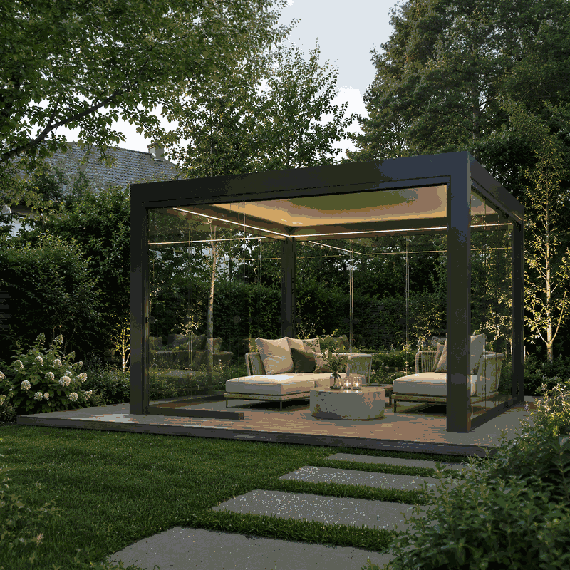
Frame, foundations, drainage and electrics must be planned together. Deciding cable routes after erection can leave exposed wiring, needless holes or inaccessible connection points. Early coordination among the owner, pergola fitter and electrical contractor helps avoid these problems.
This guidance covers project coordination. It does not replace the chosen model’s documents or assessment and work by a qualified electrical contractor. Ratings, protection and Irish requirements must be verified for the equipment and site.
What may need an electrical supply?
The roof actuator is the main electrical load. Depending on the system, power may also serve a controller, receiver, power unit, wall control, integrated lights or sensors. Handheld remotes are normally separate from fixed wiring but still need a compatible receiver on the pergola.
Electrical layouts vary between bioclimatic pergola designs . Some motors connect through a dedicated power unit or proprietary controller, while others use a different supply arrangement. Never decide the voltage, conductor type or connection method from the frame’s appearance.
- Roof actuator: drives the louvres and requires an identified source of power.
- Control equipment: receives instructions from compatible switches, handsets or sensors.
- Lights: can be built in, attached to the surface or designed as a separate installation.
- Possible additions: may include sensing equipment or powered components in later side enclosures.
Information to confirm before first-fix electrical work
Choose the precise model before cutting channels, drilling finishes or placing underground wiring. Start by reviewing the guidance on classic and bioclimatic pergola choices, on attached and freestanding layouts and on selecting an appropriate pergola size so the main construction decisions are already settled.
| Item to establish | Its effect on planning |
|---|---|
| Confirmed model and specification | Identifies the motor, control gear, lighting options and approved connection areas. |
| Frame orientation and post layout | Indicates safe cable exit positions clear of footings and water routes. |
| Location of motor and controller | Avoids bringing the incoming cable to the opposite side. |
| Current manufacturer electrical documents | Provide the authoritative connection details and compatibility limits. |
| Chosen control positions | Shape the routes to switches, controllers and any secondary operating points. |
| Lighting and genuine expansion plans | Support useful provision without fitting equipment that may never be used. |
Match the intended pergola collection to its latest assembly instructions as well. General illustrations and catalogue photographs cannot define an electrical first fix.

Coordinate the frame and electrics on one drawing
Base the electrical layout on the dimensioned foundation and assembly drawing. Mark the building supply, pergola axes, posts, footings, terrace build-up, drainage, cable routes and outlets. The pergola base and foundation guide explains why the supporting work needs resolution ahead of assembly.
Wiring must stay outside anchor zones and should not surface where roof water is discharged. Position conduit ends so posts cannot crush them and fixings cannot penetrate them. On an existing terrace, include the finished levels, waterproofing system and movement joints in the assessment.
Establish the planning position before construction starts. The local overview of Irish planning checks for pergolas offers a starting point, but exempt development in the Republic of Ireland is conditional. Ask the relevant planning authority about the property, existing structures, site restrictions and proposed classification.
Cable approaches for standalone and attached pergolas
Standalone arrangement
A freestanding pergola often receives power underground at a nominated post. The contractor must select the route, burial arrangement, impact protection, cable and entry detail for the site conditions. Conduit only helps when its bore, curves, seals and endpoint are suitable for the intended wiring.
Set the outlet from the measured assembly plan rather than an approximate footing position. Otherwise, it may emerge beneath the base plate or beyond the hollow post section. The Bloomcabin freestanding pergola overview.
Attached arrangement
An attached pergola may be supplied from the house, but the shortest route may be unsuitable. Consider insulation, façade layers, damp protection, structural elements and frame fixings. Seal every wall opening against weather in a manner appropriate to its construction.
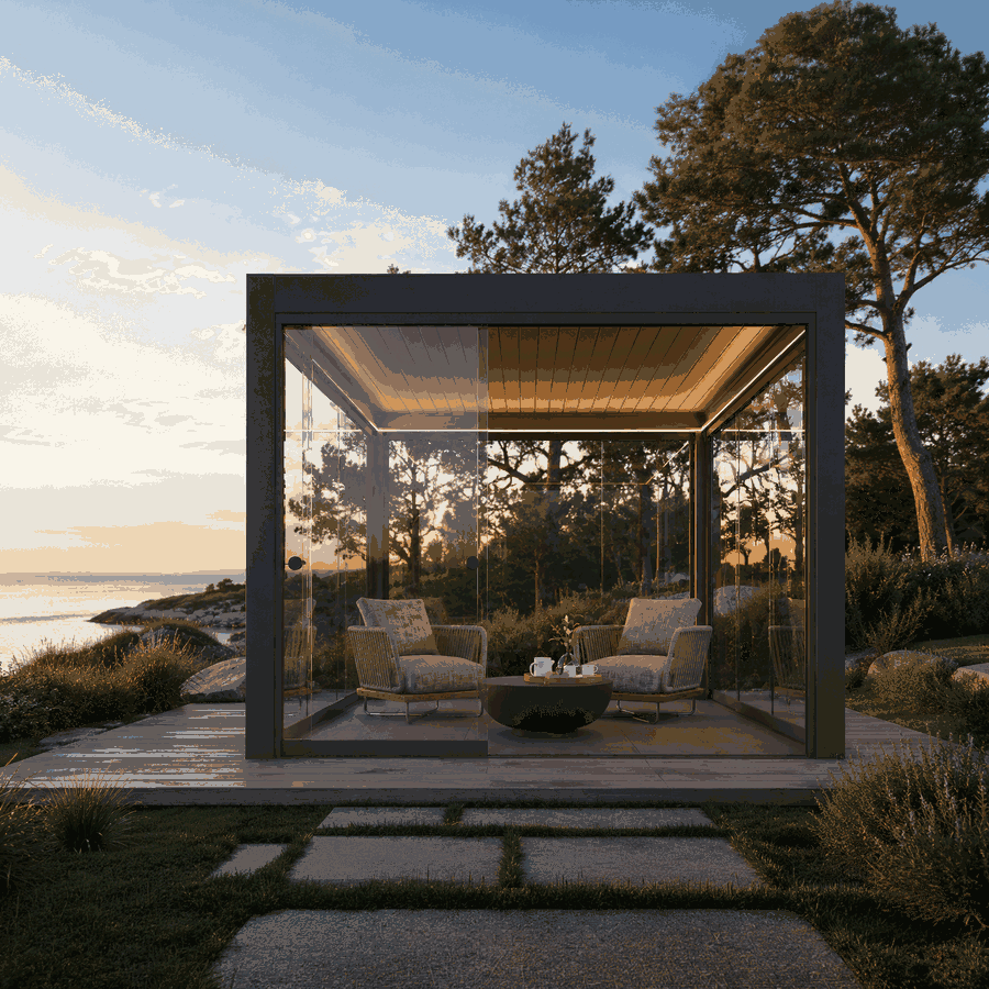
Confirm the motor and controller side before forming the route. The selected attached-pergola specification governs that decision; perspective artwork is not accurate enough for cable placement.
Design the circuit from verified equipment data
The contractor must assess load, cable length, installation conditions, exposure, protective design and the existing distribution board. These determine conductor size, protective devices, residual-current protection and whether a dedicated circuit is needed. Accessories, models and properties differ, so generic values are unreliable.
The drive and lights can share a source or use separate supplies where the equipment instructions and electrical design permit. Independent switching may make diagnosis easier because a lighting defect need not disable the roof. Extra complexity should still have a defined purpose.
A nearby outdoor socket does not prove suitability. Its circuit, condition, capacity and protection require assessment. Temporary extension leads are not a substitute for a permanent outdoor electrical installation.
Distinguish power wiring from control connections
Conductors serving unlike voltages or signals cannot be grouped or joined casually. The selected system determines suitable separation, cable construction and enclosures, together with the requirements applicable to the installation. Makeshift joints from proprietary motor leads into house wiring are especially inappropriate.
Label both ends of every cable permanently. Photograph open routes and record fixed reference points on the plan. Identify ducts ending at different posts. A draw cord helps later cable work but does not prove that a duct remains suitable.
Allow access to the actuator and controller
Keep the actuator, junction enclosure and controller accessible while protecting them from exposure and unnecessary view. Service access does not mean leaving parts open; it lets a specialist reach them without needlessly removing the supporting frame, roof louvres or fixed panels.
Fit control gear only in the orientation and environment approved for it. Trace rainwater, condensation and direct exposure, and avoid areas where heat could collect. For a Bloomcabin pergola with motorised louvres , the instructions for that model take precedence over customary site practice.
Shape the lighting around its purpose
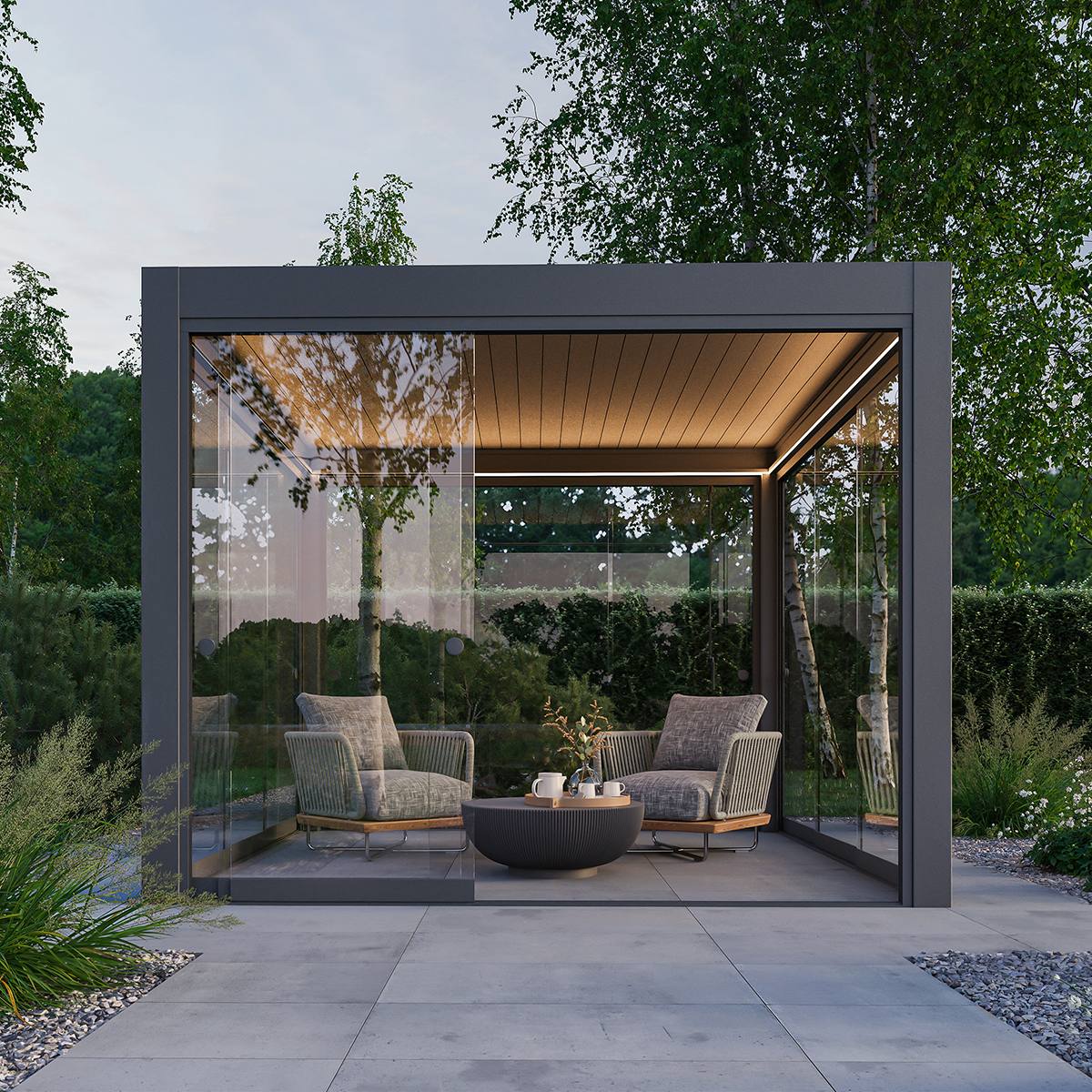
Lighting affects both usability and appearance. Arrange it to serve tables and routes without glare for seated users or troublesome reflections in glazing. Explore alternative layouts in the terrace and garden pergola ideas.
Built-in lights must be intended for the selected pergola or explicitly confirmed as compatible. Drilling profiles may damage finishes, drainage or cable channels. Surface-mounted fittings also require suitable supports and a supply designed for their outdoor position.
Points to resolve when laying out the lights
- Is the priority a dining table, circulation space or broad roof illumination?
- Will one control operate everything, or should the light be divided into zones?
- Could nearby windows or proposed glass sides create unwanted reflections?
- Which accessible location can accommodate drivers, power units or controllers?
- Will users operate the system from wall controls, a compatible handset or building automation?
- Does the lighting need to work while power to the louvre actuator is isolated?
When comparing fixed and opening roofs, also read about glass roofing and bioclimatic louvres because the roof form changes how illumination works.
Make measured provision for future additions
A labelled spare duct, recorded cable route or free space in an accessible connection area may be useful. Do not energise speculative wiring for unidentified equipment. Future accessories may need different voltages, control protocols or connection points.
Proposed glazing needs early coordination. The article about fixed and sliding glazing for pergolas compares the construction methods. Keep cable outlets, service covers and switches away from tracks, moving panels and fixing areas.
Suggested order for the work
- Define use and pergola type: choose size, mounting, roof operation, lighting and possible side enclosures.
- Survey the site: record buildings, levels, terrace build-up, foundations, drainage and existing services.
- Check product documents: confirm the actuator side, ratings, controls and intended cable entries.
- Prepare one trade plan: give the fitter, foundation contractor and electrician identical dimensions and reference points.
- Prepare cable routes: form, label and photograph suitable routes and penetrations before covering them.
- Complete foundations and surfaces: protect cable ends and recheck their positions against the assembly drawing.
- Erect the pergola: use designated cable spaces only; never drill frame profiles ad hoc.
- Make the connection: the contractor tests, connects and documents the specific system.
- Carry out functional checks: check roof movement, controls, lighting and isolation.
For help choosing the structure itself, see the buyer’s guide to aluminium pergolas and browse the Bloomcabin pergola selection .
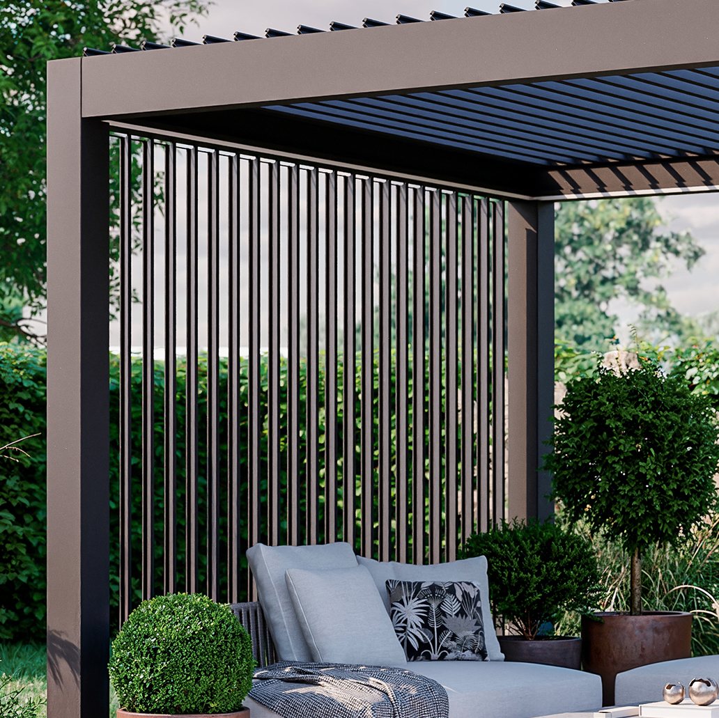
Checks before delivery and assembly
- Delivered model, specification and documents match the plan.
- Store components safely and dry without blocking the work area.
- Mark the selected post and actuator side on the site plan.
- Foundations and fixing surfaces are checked and ready.
- Each cable appears inside its agreed connection zone.
- Cable ends are isolated, protected and clearly labelled.
- Connection and control components are fully identified.
- The contractor knows the date for testing and final connection.
- Drilling, assembly and service areas remain accessible.
Where a discrepancy remains, use the Bloomcabin enquiry page before erection begins. Correcting the plan early is easier than moving finished wiring.
Test and commission the roof, controls and lights
Before energising the actuator, clear tools, packaging and loose fixings from the path of every louvre. Complete the electrical tests first. Operate the roof gradually, watching its travel and end positions and listening for unfamiliar noise.
Configure handsets and wall controls exactly as their own instructions specify, then try each command separately. Check lighting zones, dimming and switch-off functions only if the installed equipment includes them. Do not enable a sensor until its position, function and response have been verified.
Stop if the actuator jolts, sounds abnormal or travels the wrong way; repeated attempts can worsen a fault. Isolate the electrical source and arrange competent inspection of the frame, connections and settings.
Routine observation and fault diagnosis
Inspect visible electrical parts after building work, harsh weather or changes around the terrace. Look for damaged insulation, displaced covers, moisture marks and trapped cable. Keep drainage passages and aluminium surfaces clear; the guide to maintaining aluminium garden structures provides broader care advice.
If something fails, determine whether the fault is limited to the roof, the lights or every function. The user may check normal controls, obvious obstructions and visible isolation status without opening an electrical enclosure. For weather-related use, consult winter operation of a pergola.
Include other Bloomcabin buildings in the services layout
When one property contains several garden structures, plot them all on a single location and utilities drawing. These might comprise a pergola, conservatory or greenhouse, garden building and outdoor sauna. Routes can be coordinated, but that does not establish that unrelated loads belong on one circuit.
A sauna such as the Elma S garden sauna serves a different purpose and presents a different electrical brief from a louvre actuator. Work from the documents issued for each structure. Company and range information appears under About Bloomcabin and within Useful Information .
Questions customers often ask
May the supply be prepared before the pergola arrives?
Yes, if approved drawings and electrical data for the ordered model are available. Confirm the actuator side and connection area. If either remains undecided, end the route at an accessible handover point.
Is a nearby external socket sufficient?
Not without assessment. A contractor must examine the socket, cable, protection, current load and suitability for permanent use. Proximity to the pergola proves nothing.
Do all louvred roofs use an identical motor voltage?
No. Actuators, controllers and power units differ. Follow the labels and technical documents supplied with the equipment.
May the roof drive and lights share a circuit?
Possibly, depending on loads, controls and the existing installation. Separation may simplify operation and diagnosis, but the electrical contractor must determine the project-specific design.
Is it acceptable to route a cable inside a post?
Only where the pergola provides an approved route. Keep the cable clear of drainage, sharp edges, fixings and service areas. Never improvise by drilling profiles.
Could lights be installed at a later date?
An upgrade may be possible, especially with an accessible, documented route. Confirm that the fittings, supports, outdoor conditions and electrical installation are mutually compatible before work starts.
What makes a suitable position for a wall control?
Choose an accessible place that preferably allows the operator to see the roof move. Consider weather exposure, building use, children’s access and any future glazing.
Should the roof be moved from somewhere it cannot be seen?
Moving the roof without seeing it may conceal people or obstructions. Follow the manufacturer’s operating method and safety instructions. Wireless range alone does not make an operating position suitable.
How does later glazing affect the plan?
Glass panels may change routes, fixing areas, reflections and switch access. Keep their tracks clear of cables and enclosures. Record the proposed extension on the original site plan.
Who should complete the permanent electrical work?
Engage a suitably qualified contractor. Ask whether the installation includes Restricted Electrical Works. If it does, Irish rules require a Registered Electrical Contractor to perform and certify the work through the applicable completion-certificate process.
What project records are worth retaining?
Retain the model reference, assembly and electrical manuals, marked circuit or route plan, test records, concealed-work photographs, labels and details of later alterations. Keep each record clearly linked to its installation.
What if the first fix conflicts with the supplied documents?
Pause both connection and assembly. Ask the supplier, pergola fitter and electrical contractor to resolve the difference. Do not bridge the mismatch with an improvised extension or an adapter that has not been verified.
Final coordination review
- The ordered model, orientation and position are confirmed.
- Written information covers the actuator, controller and lighting equipment.
- One measured drawing aligns foundations, rainwater management and cable routes.
- The supply ends at the confirmed connection point.
- Power, signalling and control conductors have unambiguous functions.
- Service access remains available after assembly.
- Future glazing and electrical additions are included.
- Every cable and control point is labelled and documented.
- Connection, testing and commissioning are arranged with the contractor.
Good electrical planning is almost invisible in the completed pergola. Its value appears in reliable controls, practical servicing and systematic fault-finding. Related design and technical articles are available in the Bloomcabin articles and Planning Resources area.
